1592001520 XC10CX - XC30CX GB rel1.0 08.08.2012 XC30XC 1/4
Digital controller for CDU management
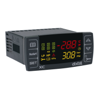
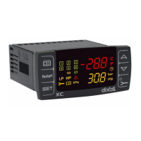
XC10CX and XC30CX
1. GENERAL WARNING
1.1 PLEASE READ BEFORE USING THIS MANUAL
• This manual is part of the product and should be kept near the instrument for easy and quick
reference.
• The instrument shall not be used for purposes different from those described hereunder. It
cannot be used as a safety device.
• Check the application limits before proceeding.
• Dixell Srl reserves the right to change the composition of its products, even without notice,
ensuring the same and unchanged functionality.
1.2
SAFETY PRECAUTIONS
• Check the supply voltage is correct before connecting the instrument.
• Do not expose to water or moisture: use the controller only within the operating limits avoiding
sudden temperature changes with high atmospheric humidity to prevent formation of
condensation
• Warning: disconnect all electrical connections before any kind of maintenance.
• Fit the probe where it is not accessible by the End User. The instrument must not be opened.
• In case of failure or faulty operation send the instrument back to the distributor or to “Dixell S.r.l.”
(see address) with a detailed description of the fault.
• Consider the maximum current which can be applied to each relay (see Technical Data).
• Ensure that the wires for probes, loads and the power supply are separated and far enough from
each other, without crossing or intertwining.
• In case of applications in industrial environments, the use of mains filters (our mod. FT1) in
parallel with inductive loads could be useful.
2. GENERAL DESCRIPTION
Model XC30CX, format 32x74mm, is a digital thermostat for condensing unit applications. It provides
three digital (relay) outputs, one for the compressor and the other ones to control the fans. It is also
provided with 2 NTC or ratiometric probe inputs, to be used on the suction and condenser line. Several
digital inputs can operate to manage the condensing unit safeties. The HOT-KEY output allows to
program the controller by means the HOT-KEY programming key. The instrument is fully configurable
through special parameters that can be easily programmed through the keyboard.
Model XC10CX differs from the XC30CX on the digital output number. In fact, the XC10CX has only
one digital output, which is used to control the compressor.
3. CONTROLLING LOADS
3.1 COMPRESSOR
The regulation is performed according to
the pressure measured by the suction
probe P1.
The compressor cut in is give by the Cin
parameter.
The compressor cut out is give by the
Cou parameter.
In case of fault in the regulation probe the start and stop of the compressor are timed through
parameters Con and CoF.
3.2 FAN MANAGEMENT (ONLY FOR XC30CX)
The XC30CX is able to control 1 or 2 condenser fans.
A direct regulation is performed (cooling). It depends on the parameters:
SF1
Set point for fan1 (with NTC probe: -40°C to SF2 or 40°F to SF2; with pressure probe:
P2i to SF2 bar/PSI/kPA)
HF1
Differential for fan 1 (0.1 to 10.0°C/bar; 1 to 100°F/PSI)
SF2
Set point for fan2 (with NTC probe: SF1 to 110°C or SF1 to 230°F;
with pressure probe: SF1 to P2E bar/PSI/kPA)
HF2
Differential for fan 2 (0.1 to 10.0°C/bar; 1 to 100°F/PSI/kPA)
A fan is switched on when the temperature (pressure) is higher than SF1+HF1 and switched off when
it comes back to SF1, as explained in the following picture
F1
F2
3.3 FAN CYCLING (ONLY FOR XC30CX)
To share the running hours between the 2 fans, the XC30CX will record the operating hours of each
fan. The controller will rotate the fan activation and de-activation to share the operating hours between
the 2 fans.
Note: with only one fan, it will be activated with T>SF1+HF1 and switched off with T<SF1.
4. FRONT PANEL COMMANDS
To display target set point; in programming mode it selects a parameter or confirm
an operation.
(RESTART) It depends on the rSC parameter; with rSC=rSt it allows a manual
restart and a “dead band reset”; with rSC=nP only the dead band reset is allowed.
(UP) To see the condenser temperature for 5 sec; in programming mode it browses
the parameter codes or increases the displayed value.
(DOWN) To see the dLt temperature; in programming mode it browses the
parameter codes or decreases the displayed value.
(SERVICE) To enter the service menu.
(Alarm menu) To enter the Alarm menu.
KEY COMBINATIONS:
+
To lock & unlock the keyboard.
+
To enter in programming mode.
+
To return to the suction pressure display.
4.1 USE OF LEDS
Each LED function is described in the following table.
LED MODE FUNCTION
ON Compressor enabled
Flashing Anti-short cycle delay enabled
1
ON Fan1 enabled (only for XC30CX)
2
ON Fans enabled (only for XC30CX)
kPA
ON kPA display
Flashing Programming mode
bar
ON bar display
Flashing Programming mode
PSI
ON PSI display
Flashing Programming mode
ON You’re browsing the service menu
Flashing A new alarm happened
ON You’re browsing the alarm menu
ON An alarm is occurring
5. OTHER FUNCTIONS
5.1 PRESSURE PROBE ERROR BY-PASS AT START UP
If a pressure probe error occurs at start-up, it will be by-passed for the P1d time, and the compressor
will be switched on when the following conditions are satisfied:
- odS, regulation delay at start up, is expired.
- With di1=Y, the thermostat digital input 14-17 is enabled.
- The HP digital input or the dLt temperature is not locking the regulation.
In this period the controller displays the flashing label P1E.
If during the P1d time the pressure probe error recovers, the standard regulation will start, otherwise,
when P1d expires the pressure probe error P1 will be signaled and the compressor will be switched on
and off cyclically with Con and CoF period.
5.2 PRESSURE PROBE ERROR BY-PASS WHEN THE COMPRESSOR IS NOT
WORKING
When the compressor is switched off the pressure probe error is not signalled. In this case if the
pressure raises and exceeds the pressure probe range, the controller will display the last value
flashing.
In this situation the compressor will restart when:
a. With di1=Y: the thermostat digital input (14-17) is enabled.
b. With di1=n: as soon as the delays for the compressor restart are expired.
c. If the compressor was switched off because of HP safety digital input or because of a
too high dLt temperature, it will be able to restart as soon as these conditions are
removed.
5.3 RESET DEAD BAND
If the pressure value is in the range [Cou to Cin] and the compressor relay is off, it’s possible to force
it keeping the RESTART key pressed for 2 sec. The compressor will run till the Cou threshold is
reached.