1592001520 XC10CX - XC30CX GB rel1.0 08.08.2012 XC30XC 3/4
7.1 HOW TO SEE THE ALARM COUNTERS
1. Push and release ALR key.
2. The controller will show the “HP” label.
3. Push SET key to see the number of activations.
4. The controller will show the “dLt” label.
5. Push the SET key to see the number of activations.
6. The controller will show the “LoC” label.
7. Push the SET key to see the number of activations.
8. SERVICE MENU
In the SERVICE menu are stored the following information:
• Number of compressor activations: StH (0 to 999, res. 1000); StL (0 to 999, res. 1)
ES: StH=22 and StL=568: the total number of compressor activations is 22568.
• Compressor working time (hours): CHH (0 to 65, res. 1000); CHL (0 to 999, res. 1).
NOTE: When the 65535 value is reached, the storing will be locked and the H_C alarm
will appear.
To reset the alarm: enter programming mode and set rCh=Y.
• Fan1 working time (hours): F1H (0 to 65, res. 1000); F1L (0 to 999; res. 1).
NOTE: When the 65535 value is reached, the storing will be locked and the H_F alarm
will appear.
To reset the alarm: enter programming mode and set rFh=Y.
• Fan2 working time (hours): F2H (0 to 65, res. 1000); F2L (0 to 999; res. 1).
NOTE: When the 65535 value is reached, the storing will be locked and the H_F alarm
will appear.
To reset the alarm: enter programming mode and set rFh=Y.
8.1 HOW TO ENTER THE SERVICE MENU
Keep SERVICE key pressed 3 sec. After that the menu StH, StL, CHH, CHL, F1H, F1L, F2H and F2L
will be showed.
To exit: push and release SERVICE key or both SET+UP keys.
9. PARAMETERS
LABEL DESCRIPTION RANGE
COMPRESSOR REGULATION
Cin Compressor cut in CoU to US bar/PSI/kPA
CoU Compressor cut out LS to Cin bar/PSI/kPA
LS Minimum set point P1i to Cou bar/PSI/kPA
US
Maximum set point Cin to P1E bar/PSI/kPA
odS Outputs delay at start up 0 to 255 sec
AC Anti-short cycle delay 6 to 900 sec
ono
Minimum time between two compressor starts 0 to 15 min
Con Compressor ON time with faulty probe 0 to 255 min
CoF
Compressor OFF time with faulty probe 0 to 255 min
FAN REGULATION (ONLY FOR XC30CX)
SF1
Set point for fan1
P2C=ntC: [-40.0°C to SF2] [-40°F to SF2] P2C=0-5:
P2i to SF2 bar/PSI/kPA
HF1
Fan 1 differential
°C [0.1 to 10.0] F [1 to 100]
bar [0.1 to 100 PSI [1 to 100]
kPA [1 tp 100]
SF2
Set point for fan2
P2C=NTC: [SF1 to 110.0°C] [SF1 to 230°F]
P2C=0-5: SF1 to P2E bar/PSI/kPA
HF2
Fan 2 differential
°C [0.1 to 10.0] F [1 to 100]
bar [0.1 to 100 PSI [1 to 100]
kPA [1 tp 100]
nFA
Number of fans on with P2 fault 0 to 2
PROBE SETTING
P1C Probe 1 configuration (9-10-11) (only for XC30CX) 0-5 = ratiometric; ntC
P1i
Start scale for probe 1
°C [-50 to 110] °F [-58 to 230]
bar [-1.0 to P2E] PSI [-15 to P2E]
kPA [-100 to P2E]
P1E
End scale for probe 1
°C [-50 to 110] °F [-58 to 230]
bar [P1i to 99.9] PSI [P1i to 999]
kPA [P1i to 999]
P1F
Probe 1 offset
°C [-12.0 to 12.0] °F [-21 to 21]
bar [-1.2 to 1.2] PSI [-120 to 120]
kPA [-120 to 120]
P1d
Pressure probe error delay at start up 0 to 100 min
P2P
Probe 2 presence no; YES
P2C
Probe 2 configuration
0-5=ratiometric;
ntC=NTC probe
P2i
Start scale for probe 2
°C [-50 to 110] °F [-58 to 230]
bar [-1.0 to P2E] PSI [-15 to P2E]
kPA [-100 to P2E]
P2E
End scale for probe 2
°C [-50 to 110] °F [-58 to 230]
bar [-1.0 to P2E] PSI [-15 to P2E]
kPA [-100 to P2E]
P2F
Probe 2 offset
°C [-12.0 to 12.0] °F [-21 to 21]
bar [-1.2 to 1.2] PSI [-120 to 120]
kPA [-120 to 120]
P3C
Probe 3 configuration (16-17)
nu; dLt = probe PTC (990ohm);
CPA = do not set it
P3F Probe 3 offset
°C [-12.0 to 12.0]
°F [-21 to 21]
MEASUREMENT UNIT
Unt
Measurement unit for pressure: PSI, bar, kPA PSI; bar; kPA
CF
Measurement unit for temperature °C; °F
rES
Resolution for °C : decimal point, integer dE(0); in(1)
dLy
Pressure display delay 0 to 255 sec
LABEL DESCRIPTION RANGE
BUMP START FUNCTION
bMP Bump start enabling no; YES
on Compressor on time 1 to 15 sec
oFF Compressor off time 1 to 15 sec
nub Number of cycle during bump start 1 to 15
bEn
Compressor stop time for next bump start 1.0 to 23h50min, res. 10 min
DLT INPUT MANAGEMENT
doF DLT alarm temperature to stop compressor [don to 200°C] [don to 392°F]
don DLT temperature for compressor restart [-30.0°C to doF] [-22°F to doF]
ALd Stop compressor delay 0 to 255 sec
nPS
Number of activation of DLT alarm in a hour to lock
compressor
0 to 15; 0 = always automatic restart
dLF
Minimum time of compressor off with dLL alarm 0 to 15 min
HIGH CONDENSER TEMPERATURE
AU2
Condenser Temperature/Pressure threshold for
high alarm
P2C=ntC: [AH2 to 110.0°C] [AH2 to 230°F] P2C=0-
AH2 to P2E bar/PSI/kPA
AH2
Differential for high Condenser
Temperature/Pressure alarm recovery
P2C=ntC: [-40.0°C to AU2] [-40°F to AU2] P2C=0-5:
P2i to AU2 bar/PSI/kPA
Ad2
High condenser temperature alarm delay 0 to 255min
RELAY CONFIGURATION (ONLY FOR XC30CX)
tbA
Buzzer muting no; YES
oA2
Relay 1-2 configuration FAn=Fan 1 Fn2=Fan 2 ALr=Alarm relay
DIGITAL INPUT MANAGEMENT
di1 Thermostat digital input presence 14-17 no; YES
i1P Thermostat digital input polarity 14-17 oP; CL
di2 HP safety digital input presence 15-17 no; YES
i2P HP safety digital input polarity 15-17 oP; CL
HPn
HP safety digital input activation before compressor
lock
0 to 15; 0 = always automatic restart
HPF
Minimum time of compressor off with HP d.i. alarm 0 to 15 min
COUNTER RESET
rSt
Regulation restart with dLL and HPL alarm (only
for XC30CX)
no; YES
rSA
Alarm counters reset ( dLt, HP) no; YES
rCA
Compressor activation counter reset no; YES
rCH
Compressor running hours reset no; YES
rFH
Fan running hours reset (only for XC30CX) no; YES
OTHERS
dP1 P1 probe display (Probe value)
dP2 P2 probe display (Probe value)
dP3 P3 probe display (Probe value)
rEL Firmware Release Readable only
Ptb Map code Readable only
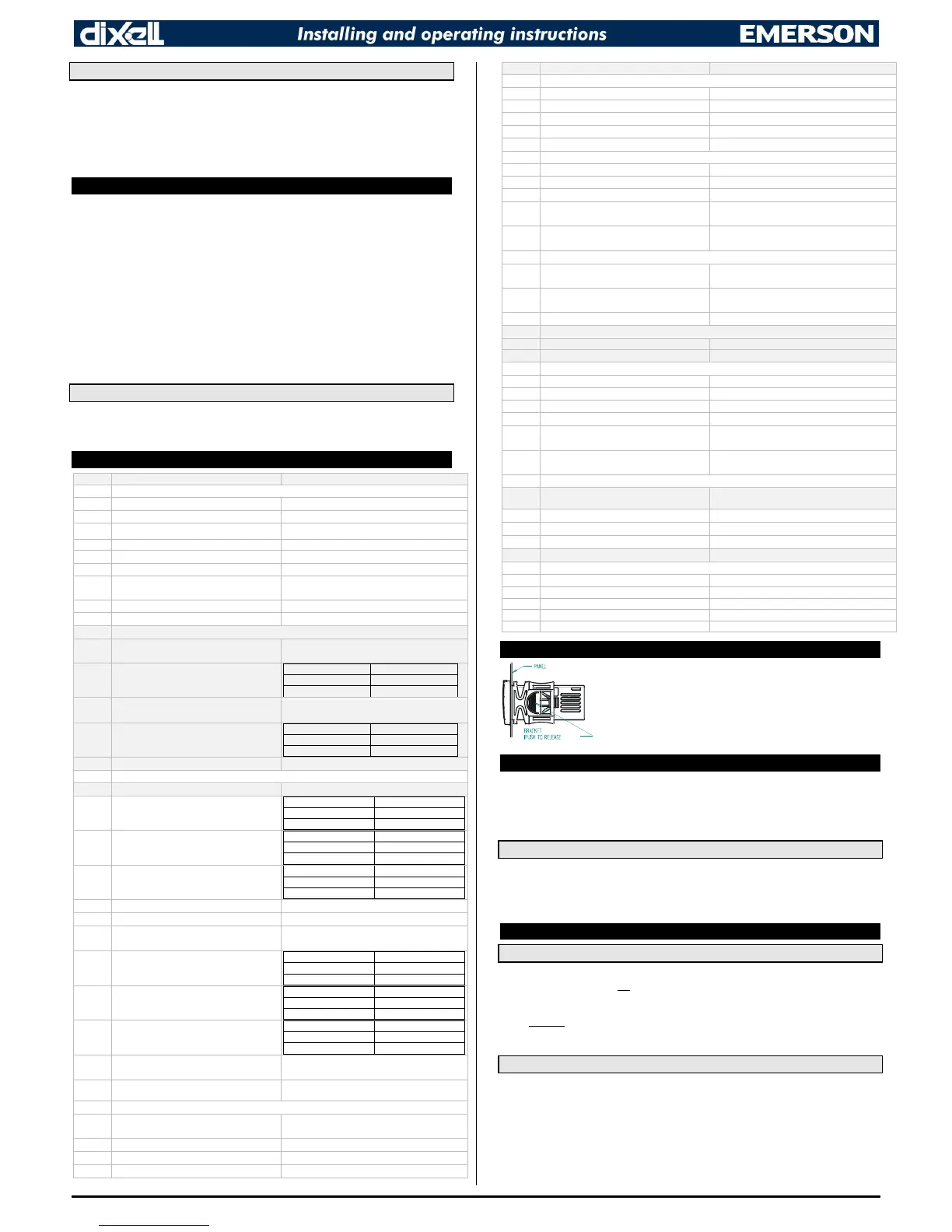
10. INSTALLATION AND MOUNTING
XC10CX and XC30CX shall be mounted on vertical panel, in a
29x71mm hole, and fixed using the special bracket supplied.
The temperature range allowed for correct operation is -10 to 55°C.
Avoid places subject to strong vibrations, corrosive gases,
excessive dirt or humidity. The same recommendations apply to
probes. Let air circulate by the cooling holes.
11. ELECTRICAL CONNECTIONS
The instrument is provided with screw terminal block to connect cables with a cross section up to
2.5mm
2
. Before connecting cables make sure the power supply complies with the instrument’s
requirements. Separate the probe cables from the power supply cables, from the outputs and the
power connections. Do not exceed the maximum current allowed on each relay, in case of heavier
loads use a suitable external relay.
11.1 PROBE CONNECTION
The probes shall be mounted with the bulb upwards to prevent damages due to casual liquid
infiltration. It is recommended to place the thermostat probe away from air streams to correctly
measure the average room temperature. Place the defrost termination probe among the evaporator
fins in the coldest place, where most ice is formed, far from heaters or from the warmest place during
defrost, to prevent premature defrost termination.
12. HOW TO USE THE HOT KEY
12.1 HOW TO PROGRAM A HOT KEY FROM THE INSTRUMENT (UPLOAD)
1. Program one controller with the front keypad.
2. When the controller is ON, insert the “HOT-KEY” and push UP button; the “uPL” message
appears followed a by a flashing “End” label.
3. Push SET button and the “End” will stop flashing.
4. Turn OFF the instrument, remove the “HOT-KEY” and then turn it ON again.
NOTE: the “Err” message appears in case of a failed programming operation. In this case push again
button if you want to restart the upload again or remove the “HOT-KEY” to abort the operation.
12.2 HOW TO PROGRAM AN INSTRUMENT USING A HOT KEY (DOWNLOAD)
1. Turn OFF the instrument.
2. Insert a pre-programmed “HOT-KEY” into the 5-PIN receptacle and then turn the Controller
ON.
3. The parameter list of the “HOT-KEY” will be automatically downloaded into the Controller
memory. The “doL” message will blink followed a by a flashing “End” label.
4. After 10 seconds the instrument will restart working with the new parameters.
5. Remove the “HOT-KEY”.
NOTE: the message “Err” is displayed for failed programming. In this case turn the unit off and then
on if you want to restart the download again or remove the “HOT-KEY” to abort the operation.

 Loading...