Do you have a question about the Emerson dixell XC650CX and is the answer not in the manual?
Verify controller software version for manual compatibility.
Important pre-use instructions, guidelines, and safety precautions.
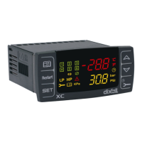
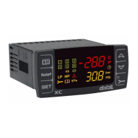
Overview of the XC650CX controller's design and function.
List of components and part numbers for the XC650CX.
Important warnings before making electrical connections.
Diagram, terminal assignments, and probe connection guidelines.
Wiring details for connecting loads (compressors, fans).
Setting up digital inputs as safety inputs and pressure switches.
Connecting analog outputs for data transmission.
Connecting the controller to a monitoring system via RS485.
Setting the refrigerant gas type (FtyP parameter) for correct operation.
Configuring pressure probe ranges (PA04, PA20, FA04, FA20).
Explanation of display information and keyboard button functions.
Meanings of icons and how to view set points.
Step-by-step guide to adjust compressor and fan set points.
Accessing user-accessible and protected parameter lists.
Procedure for modifying parameter values.
Steps to disable controller outputs during maintenance.
Displaying and resetting load running hours.
Navigating and managing alarms.
Locking and unlocking the controller's keyboard.
Uploading/downloading configurations using the HOT KEY.
Configuring plant setup and regulation types.
Configuring the suction probe type and calibration.
Configuring condenser, third/fourth probes, and fan/suction probes.
Detailed configuration options for digital inputs.
Setting display units for temperature and pressure.
Parameters related to compressor regulation modes.
Configuration for liquid injection thermostat settings.
Parameters for fan speed and operation control.
Compressor-related alarms and their causes/actions.
Fan-related alarms and their causes/actions.
Monitoring suction superheat and signaling low superheat conditions.
Configuring dynamic set points based on external temperature.
Configuration of analog output 1.
Configuration of analog output 2.
Miscellaneous parameters like alarm relay and buzzer.
Regulation for compressors with the same capacity.
Dead band control for homogeneous compressors.
Regulation for compressors with different capacities.
Example of regulation for uneven capacity compressors.
Specific handling for screw compressors.
Regulation methods for screw compressors.
How fan speed is regulated based on system conditions.
Parameters for condenser fan configuration with inverters.
Detailed steps for setting up inverter/ECI fan configurations.
Parameters for configuring the analog output linked to a temperature probe.
Step-by-step guide to configure the "free" analog output.
Verifying compressor operation using digital inputs.
Parameters and alarms for compressor running proof.
Function to prevent cabinet flooding by blocking liquid injection.
How suction superheat is detected and calculated.
Actions taken for low superheat pre-alarm and alarm.
Parameters and regulation logic for the hot gas injection valve.
Categorization of alarms and how they are signaled.
Alarms related to incorrect configuration settings.
Electronic pressure switch alarms for suction circuits.
Pressure switch alarms for suction and condensing sections.
Low pressure switch alarm for suction circuit 2.
Alarms for safety inputs and probe failures.
High/low pressure alarms for compressors and fans.
Summary table of alarm codes, causes, actions, and resets.
| Model | XC650CX |
|---|---|
| Front Panel Protection | IP65 |
| Type | Controller |
| Input Type | NTC, PTC |
| Display | LCD |
| Communication | Modbus RTU |
| Operating Temperature | -10°C to +55°C |
| Storage Temperature | -20°C to +70°C |
| Relative Humidity | 20% to 90% non-condensing |
| Resolution | 0.1 °C |
| Protection Degree | IP65 |
| Power Consumption | 5 W |
| Outputs | 2 Relay Outputs |