Do you have a question about the Emerson Dixell XC35CX and is the answer not in the manual?
Check voltage, avoid moisture, disconnect power before maintenance. Do not open.
XC35CX is a regulator for tandem condensing units. Drives compressors & ventilators.
Ensure power supply compliance, separate cables, do not exceed relay current.
Wiring diagrams for High Voltage (110/230VAC) and Low Voltage (24VAC) models.
Wiring diagram and connection details for models with 110 or 230VAC power supply.
Wiring diagram and connection details for models with 24VAC power supply.
Wiring diagrams and load configurations for high voltage models.
Wiring diagrams and load configurations for low voltage models.
Instructions for panel mounting, ambient temperature, and ventilation requirements.
Procedure for setting pressure probe ranges (P1i/P2i for 0.5V, P1E/P2E for 4.5V).
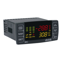
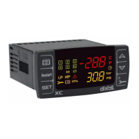
Description of the device display elements, including indicators and measurements.
Explanation of the function of each button (SET, UP, DOWN) in different modes.
Table explaining the meaning of LED status indicators and their functions.
How to view the current setpoint values for compressor (St1) and ventilator (St2).
Procedure for modifying setpoint values for compressor (St1) and ventilator (St2).
Table listing alarm codes and their corresponding meanings (e.g., HA, LA, H2).
Steps to view recorded alarm events, their labels, and durations.
Procedure for resetting the alarm list or a single displayed alarm event.
Accessing the parameter list Pr1 (user level) for configuration.
Accessing the parameter list Pr2 (protected level) for configuration.
Parameters for setting regulation bands (HY1, HY2) and limits (LS1, US1, LS2, US2).
Manages digital compressors (Scroll or Stream D4D) using modulation.
Manages inverter compressors using frequency or voltage control.
How alarms are visualized, activated, and memorized.
| Model | XC35CX |
|---|---|
| Temperature Range | NTC -50 to +110°C; PTC -55 to +150°C |
| Relay Outputs | Compressor: SPDT 8(3)A 250Vac; Defrost: SPDT 8(3)A 250Vac; Fan: SPDT 8(3)A 250Vac; Alarm: SPDT 8(3)A 250Vac |
| Communication Protocol | Modbus RTU |
| Accuracy | Better than 1% of full scale |
| Hysteresis | Adjustable |
| Resolution | 0.1 °C |
| Type | Controller |
| Display | LCD |
| Output | Relay |
| Serial output | RS485 |
| Analog output | 0-10 V / 4-20 mA |
| Mounting | DIN rail |
| Protection class | IP20 |
| Digital inputs | 2 |