Do you have a question about the Emerson Dixell XC645CX and is the answer not in the manual?
Check the software revision of the XC645CX controller.
Read this manual before using the instrument to ensure proper operation and safety.
Important safety guidelines and precautions to follow during installation and operation.
Details on the wiring kits provided with the XC645CX for connecting components.
Information about the 2-pin connectors used for digital inputs or analog outputs.
Description of 4-20mA pressure transducers compatible with the controller.
Details of the NP4-67 temperature probe for mounting on pipes.
Information on the XJ485CX converter for TTL to RS485 signal conversion.
Important warnings and guidelines before making any wiring or electrical connections.
Diagrams and instructions for making the correct wiring connections to the controller.
Instructions for connecting pressure and temperature probes to the controller.
Guidelines for connecting loads such as compressors and fans to the controller's outputs.
Details on using digital inputs for safety functions and configuration.
Instructions for connecting analog outputs for signal transmission.
Steps to connect the controller to a monitoring system via RS485 serial communication.
Procedure for setting the refrigerant type used in the system for accurate control.
Steps to calibrate and set the measurement range for connected pressure probes.
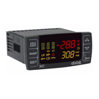
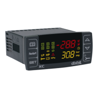
Explanation of the information shown on the controller's upper and lower displays.
Description of the function of each button on the controller's keypad.
Explanation of the various icons displayed on the controller screen.
Procedure to view the currently set points for compressor and fan control.
Steps to change the target set points for compressors and fans.
Procedure to access the user-accessible parameter list (Pr1).
Steps to access the protected parameter list (Pr2) using a security code.
Instructions for modifying parameter values within the controller's programming modes.
Procedure to temporarily disable controller outputs for maintenance purposes.
How the controller indicates when an output has been disabled.
Explanation of how the regulation behaves when some outputs are disabled.
Procedure to view the accumulated running hours for each connected load.
Steps to reset the running hours counter for individual loads.
Procedure to access and view the list of recorded alarms and their details.
Steps to lock the controller's keypad to prevent accidental changes.
Procedure to unlock the controller's keypad after it has been locked.
Steps to copy the controller's configuration to a Hot Key device.
Procedure to load a configuration from a Hot Key device into the controller.
Setting up the controller for different plant configurations and regulation types.
Options for configuring the connected temperature and pressure probes.
Configuration settings for additional digital inputs and their functions.
How to set display units for temperature, pressure, and measurement units.
Parameters and settings for regulating compressor operation and capacity.
Configuration of the liquid injection thermostat and related parameters.
Settings for regulating the operation of fans based on various parameters.
Configuration of alarms related to the compressor section of the system.
Configuration of alarms specific to the Discharge Line Temperature (DLT) section.
Configuration of alarms related to the fan operation.
Settings for monitoring and managing suction superheat levels.
Configuration of dynamic set points for fan control based on external conditions.
Settings for configuring the optional analog outputs for signal transmission.
Various other functions and settings not covered in previous sections.
Detailed explanation of digital compressor control modes and parameters.
How fans are regulated using proportional band control based on input signals.
Configuration for condenser fans driven by inverters or EC motors using analog outputs.
Setting up analog output 1 to reflect temperature values from a selected probe.
Ensuring compressors are running correctly after activation using digital inputs.
Setting up a relay to prevent liquid flooding in cabinets by blocking liquid injection.
Monitoring suction superheat and taking action based on pre-alarm and alarm thresholds.
Controlling a hot gas injection valve to increase suction superheat.
Overview of the different types of alarms and how they are signaled by the controller.
How to silence the audible alarm buzzer during an alarm condition.
A table summarizing various alarm conditions, their causes, actions, and reset methods.
| Model | XC645CX |
|---|---|
| Series | Dixell |
| Type | Controller |
| Outputs | Up to 4 relay outputs |
| Communication Protocol | Modbus RTU |
| Serial communication | RS485 |
| Front panel protection | IP65 |
| Power Supply | 230 V AC |
| Storage Temperature | -40 to 85 °C |
| Relative Humidity | 20% to 95% non-condensing |
| Display | LCD |
| Digital Inputs | 2 |
| Resolution | 0.1 °C |
| Accuracy | ±0.5 °C |
| Protection Degree | IP20 |
| Inputs | Up to 4 NTC/PTC/PT1000 probes |
| Data storage | Yes, with data logging function |