1592001440 XC645CX GB r3.4 31.10.2017.docx XC645CX 37/54
18.3 Condenser with Inverter or Ec Fans–Analog Output Setting
This configuration is used when all fans of the condensing group are ECI fans or driven by one
inverter or a chopped phase driver.
The capacity used by the inverter is proportional to the delivery pressure value inside the
regulation band (SETF-Pb/2÷ SETF+Pb/2).
18.3.1 Condenser fan configurations and Parameters
One relay is used to enable the action of the inverter.
Set the output to drive ECI or inverter fan
Minimum value for
analog output
The minimum voltage is 0V.
NOTE: verify on the inverter of ECI fan of chopped
phase driver that with this input a proper output is
supplied to the fan.
Time of analog output
at max after the start
To start the fan the controller supplies 10V output for
5s, then starts standard regulation
Maximum % variation
per minute
The analog output takes 1 min to move from the min
to the maximum
18.3.2 How to set it
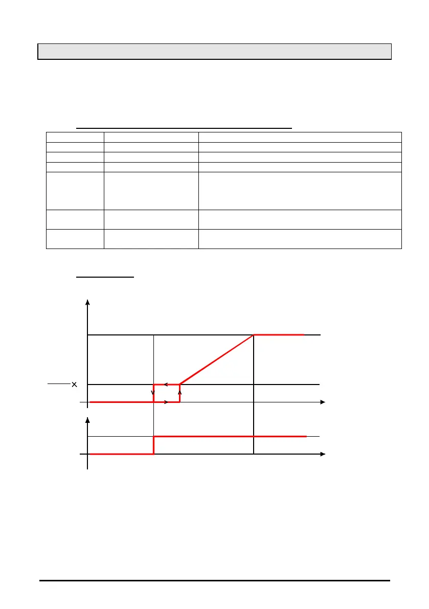
Parameters involved: oA(i) = inF; AoC = tEn, AoP = P2, AOM = 30, MPM = 100
P2
Volt
SETF-Pb/2 SETF+ Pb/2
10
0
AOM
100
10
P2
SETF-Pb/2 SETF+ Pb/2
On
OAi = inF
a. If required, set a relay to drive the invert (is used to signal to the inverter to start and stop the
regulation), by setting: oA(i) = inF inverter for fans
b. Set the kind of signal of the analog output current (4-20ma) or voltage (0-10V) by the
Analog output setting parameter “AoC”: tEn = 0÷10V output; cUr = 4-20mA output
c. Set the function of the analog output: AoF = InF
d. Set the time of the analog output at max after start up EI: Aot = 3s
e. Set the max % variation per min (MP)
f. At last set also the percentage of analog output in case of probe failure: (0 ÷ 100%)SAO
 Loading...