1598024001 XR44CX ISA GB r2.0 21.06.2012.doc XR44CX 3/4
ALL Minimum temperature alarm:
If ALC=Ab: [-55°C to ALU; -67 to ALU]
If ALC=rE: [0.0 to 50.0°C or 0 to 90°F]
when this temperature is reached the alarm is enabled, after the ALd delay time.
AFH Differential for temperature alarm recovery: (0.1 to 25.5°C; 1 to 45°F) intervention
differential for recovery of temperature alarm.
ALd
Temperature alarm delay: (0 to 255 min) time interval between the detection of an
alarm condition and alarm signalling.
dAo Exclusion of temperature alarm at start-up: (0.0 to 24h00min, res. 10min) time
interval between the detection of the temperature alarm condition after instrument power
on and alarm signalling.
OUTPUT RELAYS
oA1 First relay configuration AUX1: (dEF; FAn; ALr; LiG; AUS; onF; db; CP2; dEF2) dEF
= defrost; FAn = do not select it; ALr = alarm; LiG = light; AUS = Auxiliary relay; onF =
always on when instrument on; CP2 = second compressor; dEF2 = second defrost.
oA2 Second relay configuration AUX2: (dEF; FAn; ALr; LiG; AUS; onF; db; CP2; dEF2)
dEF = defrost; FAn = do not select it; ALr = alarm; LiG = light; AUS = Auxiliary relay;
onF = always on when instrument on; CP2 = second compressor; dEF2 = second
defrost.
oA3 Third relay configuration AUX3: (dEF; FAn; ALr; LiG; AUS; onF; db; CP2; dEF2)
dEF = defrost; FAn = do not select it; ALr = alarm; LiG = light; AUS = Auxiliary relay;
onF = always on when instrument on; CP2 = second compressor; dEF2 = second
defrost.
DIGITAL INPUTS
i1P Second digital input polarity: (oP; CL) oP = the digital input is activated by opening
the contact; CL = the digital input is activated by closing the contact.
i1F Second digital input configuration: (EAL; bAL; PAL; dor; dEF; AUS; Htr; FAn; ES)
EAL = external alarm: “EA” message is displayed; bAL = serious alarm “CA” message
is displayed; PAL = pressure switch alarm, “CA” message is displayed; dor = door
switch function; dEF = activation of a defrost cycle; AUS = auxiliary relay activation with
oAx=AUS; Htr = type of inverting action (cooling or heating); FAn = fan; ES = energy
saving.
did Digital input 1 alarm delay: (0 to 255 min) delay between the detection of the external
alarm condition and its signalling.
When i1F= PAL, it is the interval of time to calculate the number of pressure switch
activation.
nPS Number of pressure switch activation: (0 to 15) Number of activation, during the did
or d2d interval, before signalling an alarm event (i1F, i2F=PAL).
If the nPS activation during did or d2d time is reached, switch off and on the
instrument to restart normal regulation.
odC Compressor status when open door: (no; FAn; CPr;F_C;) no = normal;
FAn = normal; CPr = compressor OFF, F_C = compressor OFF.
rrd Outputs restart after door open alarm: (n; Y) n = outputs follow the odC parameter.
Y = outputs restart with a door open alarm.
HES Delta temperature during an Energy Saving cycle: (-30.0 to 30.0°C; -54 to 54°F) it
sets the increasing value of the set point [SET+HES] during the Energy Saving cycle.
OTHER
Adr Serial address: (1 to 247) identifies the instrument address when connected to a
ModBUS compatible monitoring system.
PbC Type of probe: (PtC; ntC) it allows to set the kind of probe used by the instrument:
PtC = PTC probe, ntC = NTC probe.
onF On/Off key enabling: (nU; oFF; ES) nU = disabled; oFF = enabled; ES = not set it.
dP1 Thermostat probe display.
dP2 Evaporator probe display.
dP3 Third probe display- optional.
rEL Software release for internal use.
Ptb Parameter table code: readable only.
8. DIGITAL INPUTS
The free voltage digital input is programmable by the i1F parameter.
8.1 GENERIC ALARM (I1F = EAL)
As soon as the digital input is activated the unit will wait for did time delay before signalling the EAL
alarm message. The outputs statuses don’t change. The alarm stops just after the digital input is de-
activated.
8.2 SERIOUS ALARM MODE (I1F = BAL)
When the digital input is activated, the unit will wait for did delay before signalling the CA alarm
message. The relay outputs are switched OFF. The alarm will stop as soon as the digital input is de-
activated.
8.3 PRESSURE SWITCH (I1F = PAL)
If during the interval time set by did parameter, the pressure switch has reached the number of
activation of the nPS parameter; the CA pressure alarm message will be displayed. The compressor
and the regulation are stopped. When the digital input is ON the compressor is always OFF. If the
nPS activation in the did time is reached, switch off and on the instrument to restart normal
regulation.
8.4 DOOR SWITCH INPUT (I1F = DOR)
It signals the door status and the corresponding relay output status through the odC parameter:
no = normal (any change); FAn = Fan OFF; CPr = Compressor OFF; F_C = Compressor and fan
OFF. Since the door is opened, after the delay time set through parameter doA, the door alarm is
enabled, the display shows the message dA and the regulation restarts is rtr=YES. The alarm
stops as soon as the external digital input is disabled again. With the door open, the high and low
temperature alarms are disabled.
8.5 START DEFROST (I1F = DEF)
It starts a defrost if there are the right conditions. After the defrost is finished, the normal regulation
will restart only if the digital input is disabled otherwise the instrument will wait until the “MdF” safety
time is expired.
8.6 SWITCH THE AUXILIARY RELAY (I1F = AUS)
With oA3 = AUS the digital input switched the status of the auxiliary relay
8.7 ENERGY SAVING (I1F = ES)
The Energy Saving function allows to change the set point value as the result of the SET+ HES
(parameter) sum. This function is enabled until the digital input is activated.
8.8 ON OFF FUNCTION (I1F = ONF)
To switch the controller on and off.
8.9 DIGITAL INPUT POLARITY
The digital input polarity depends on the i1P parameter.
i1P = CL: the input is activated by closing the contact.
i1P = oP: the input is activated by opening the contact
9. TTL SERIAL LINE – FOR MONITORING SYSTEMS
The TTL serial line, available through the HOT KEY connector, allows to connect the instrument to a
monitoring system ModBUS-RTU compatible such as the XWEB500. The connection needs a special
TTL/RS485 adapter: the XJ485CX.
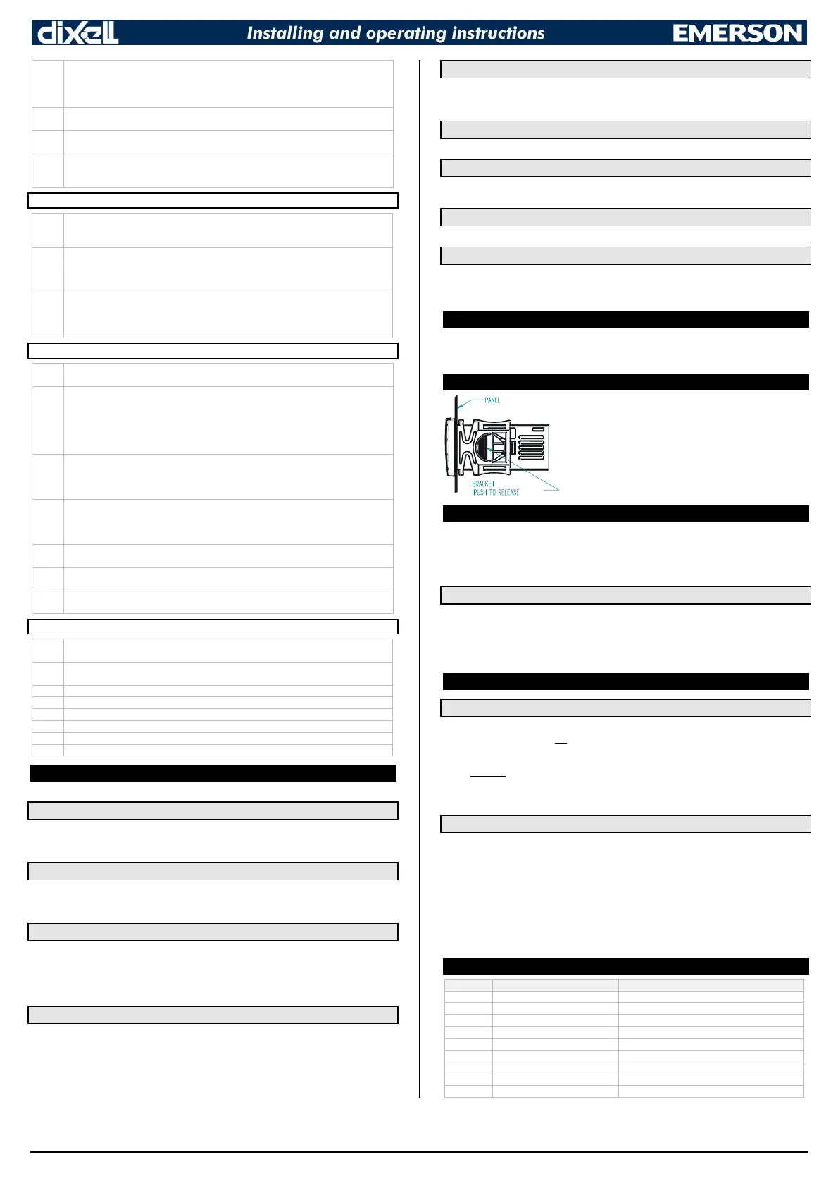
10. INSTALLATION AND MOUNTING
Instrument XR70CX shall be mounted on vertical panel, in a 29x71
mm hole, and fixed using the special bracket supplied.
The temperature range allowed for correct operation is 0 to 60°C.
Avoid places subject to strong vibrations, corrosive gases,
excessive dirt or humidity. The same recommendations apply to
probes. Let air circulate by the cooling holes.
11. ELECTRICAL CONNECTIONS
The instrument is provided with screw terminal block to connect cables with a cross section up to
2.5mm
2
. Before connecting cables make sure the power supply complies with the instrument’s
requirements. Separate the probe cables from the power supply cables, from the outputs and the
power connections. Do not exceed the maximum current allowed on each relay, in case of heavier
loads use a suitable external relay.
11.1 PROBE CONNECTION
The probes shall be mounted with the bulb upwards to prevent damages due to casual liquid
infiltration. It is recommended to place the thermostat probe away from air streams to correctly
measure the average room temperature. Place the defrost termination probe among the evaporator
fins in the coldest place, where most ice is formed, far from heaters or from the warmest place during
defrost, to prevent premature defrost termination.
12. USE THE HOT KEY
12.1 HOW TO: PROGRAM A HOT KEY FROM THE INSTRUMENT (UPLOAD)
1. Program one controller with the front keypad.
2. When the controller is ON, insert the “HOT-KEY” and push UP button; the “uPL” message
appears followed a by a flashing “End” label.
3. Push SET button and the “End” will stop flashing.
4. Turn OFF the instrument, remove the “HOT-KEY” and then turn it ON again.
NOTE: the “Err” message appears in case of a failed programming operation. In this case push again
button if you want to restart the upload again or remove the “HOT-KEY” to abort the operation.
12.2 HOW TO: PROGRAM AN INSTRUMENT USING A HOT KEY (DOWNLOAD)
1. Turn OFF the instrument.
2. Insert a pre-programmed “HOT-KEY” into the 5-PIN receptacle and then turn the Controller
ON.
3. The parameter list of the “HOT-KEY” will be automatically downloaded into the Controller
memory. The “doL” message will blink followed a by a flashing “End” label.
4. After 10 seconds the instrument will restart working with the new parameters.
5. Remove the “HOT-KEY”.
NOTE: the message “Err” is displayed for failed programming. In this case turn the unit off and then
on if you want to restart the download again or remove the “HOT-KEY” to abort the operation.
13. ALARM SIGNALS
Message Cause Outputs
P1 Room probe failure Compressor output acc. to par. Con and CoF
P2 Evaporator probe failure Defrost end is timed
P3 Third probe failure Outputs unchanged
HA Maximum temperature alarm Outputs unchanged.
LA Minimum temperature alarm Outputs unchanged.
dA Door open Compressor and fans restarts
EA External alarm Output unchanged.
CA Serious external alarm (i2F=bAL)
All outputs OFF.
CA Pressure switch alarm (i2F=PAL) All outputs OFF

 Loading...


