1592033070 XR70CHC EN r1.0 2019.01.30 XR70CHC 2/6
8 DEFROST
8.1 DEFROST MODE
Any defrost operation can be controlled in the following way:
• EdF=rtC: by using an internal real-time clock (only for models equipped with RTC)
• EdF=in: timed defrost, in this case a new defrost will start as soon as the idF timer elapses
8.2 TIMED OR PROBE CONTROLLED MODE
Two defrost modes are available: timed or controlled by the evaporator’s probe. A couple of
parameters is used to control the interval between defrost cycles (idF) and its maximum length (MdF).
During the defrost cycle is possible to select some different display indications by using the dFd
parameter. These modes are available with any kind of defrost type:
• tdF=EL: electric heater defrost
• tdF=in: hot gas defrost
9 DIGITAL OUTPUT CONFIGURATION
Depending on the model, one or more digital outputs (relays) can be configurated with one of the following
functionalities.
9.1 CONFIGURABLE OUTPUT
9.1.1 LIGHT OUTPUT
With oAx=LiG the relay operates as light output.
9.1.2 DIGITAL OUTPUT ACTIVATION
The auxiliary output can be managed by digital inputs (oAx=AUS, i1F or i2F=AUS): with oAx=AUS
and i1F, i2F=AUS the output is switched on and off following the linked digital input status.
9.1.3 AUXILIARY THERMOSTAT
The auxiliary regulator can be used to manage the auxiliary output. Here follow the involved
parameters:
• ACH: kind of regulation for the auxiliary relay: Ht = heating; CL = cooling
• SAA: set point for auxiliary relay
• SHY: differential for auxiliary relay
• ArP: probe for auxiliary relay
• Sdd: auxiliary output off during defrost
9.1.4 TIMED ACTIVATION
The following parameters can be used to define fixed activation and deactivation intervals.
• btA: base time for auxiliary output activation and deactivation intervals
• Ato: auxiliary activation interval
• AtF: auxiliary deactivation interval
9.1.5 GENERAL NOTES
if oAx=AUS and ArP=nP (no probe for auxiliary digital output) the AUX output can be managed:
• by digital input if i1F=AUS or i2F=AUS
• by auxiliary button (if set as AUS)
• by serial command (Modbus protocol)
• by fixed interval of time if Ato>0 and AtF>0 (if Ato=0 or AtF=0 the auxiliary output is disabled)
9.2 ON/OFF OUTPUT (OAX = ONF)
When oAx=onF, the output is activated when the controller is turned on and de-activated when the
controller is turned off.
9.3 DEAD BAND REGULATION
With oAx=db the output can be used to control, for example, a heater element. It is used to implement
a dead band regulation. If so:
• oAx=db cut in is SET-HY
• oA1=db cut out is SET
9.4 ALARM OUTPUT
With oAx=ALr the output operates as alarm output. It is activated every time an alarm happens. Its
status depends on the tbA parameter: if tbA=Y, the output is deactivated by pressing any key.
If tbA=n, the alarm output stays on until the alarm condition recovers.
9.5 ACTIVATION DURING ENERGY SAVING CYCLES
With oAx=HES, the output is activated when the energy saving cycle begins.
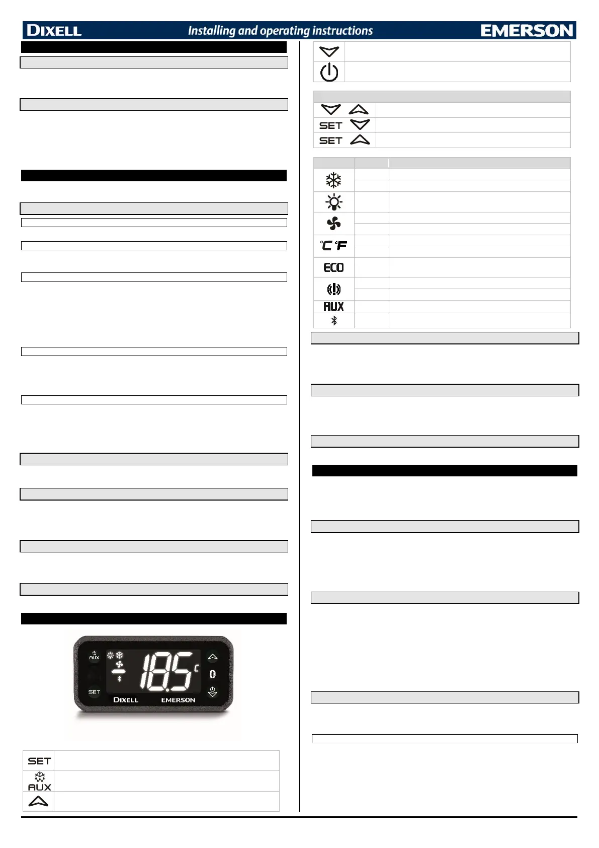
10 FRONT PANEL COMMANDS
Press to display target set point and the real set point. When in programming mode,
it selects a parameter or confirms an operation
(AUX/DEF) Programmable button, see par. LGC and LG2
(UP) In programming mode it browses the parameter codes or increases the
displayed value. Other functions related to par. UPC and UP2 (if available)
(DOWN) In programming mode it browses the parameter codes or decreases the
displayed value. Other functions related to the par. dnC and dn2 (if available)
(ONOFF) Keep it pressed for 3 sec to switch on and off the device
To lock or unlock the keyboard
To enter in programming mode
To return to room temperature display
Anti-short cycle delay enabled (AC parameter)
Ventilator output enabled
Ventilator delay after defrost
Energy saving mode active
An alarm condition is present
Start-up operations are pending
Auxiliary output is activated
Bluetooth connection enabled
10.1 SET POINT MENU
The SET key gives access to a quick menu where it is possible to see:
• the set point value
• the real set point value (rSE)
Push and release the SET key five times or wait for 60 sec to return to normal visualization.
10.2 CHANGE THE SETPOINT
1. Push the SET key for more than 3 sec to change the Set point value;
2. The value of the set point will be displayed and the “°C” LED starts blinking;
3. To change the Set value, push the UP or DOWN button.
4. To memorise the new set point value, push the SET button again or wait for 60 sec.
10.3 START A MANUAL DEFROST
Push the DEFROST
button for more than 3 sec to start a manual defrost.
11 PARAMETER MENU
The device has a parameter menu available from keyboard and where it is possible to modify some specific
parameters. A couple of parameter levels are present:
- PR1: user menu, standard parameters are placed into this menu
- PR2: protected menu, application specific parameters are placed here. A password can be
used to protect these values from unauthorized modification.
11.1 MENU NAVIGATION
A tree-structured menu is implemented to simplify the parameter browsing and modification. Follow the button
functions (valid both in PR1 and PR2):
- SET: used to enter a submenu or a stored value
- UP and DOWN: used to scroll the menu labels, the parameters into a submenu and to modify a
parameter value
- AUX/DEF: used to go back to the upper menu level (for example, from a submenu list of
parameters to the main menu labels)
11.2 CHANGE A PARAMETER VALUE
To change a parameter value, operate as follows:
1. Enter the Programming mode by pressing the SET+DOWN buttons for 3 sec (“°C” LED starts
blinking).
2. Select the required parameter. Press the SET button to display its value
3. Use UP or DOWN buttons to change its value.
4. Press SET to store the new value and move to the following parameter.
To exit: Press SET+UP buttons or waits for 15 sec without pressing any button.
NOTE: The modified value will be stored even if the programming mode ends by timeout.
11.3 PROTECTED LEVEL
The Protected Level has all the parameters of the instrument. This level is password protected. The
default password is: “000”. It is strongly recommended to change the standard password after ending
the installing operations.
11.3.1 ENTER THE PROTECTED LEVEL
1. Enter the Programming mode by pressing SET+DOWN buttons for 3 sec (°C or °F
LED starts
blinking)
2. Released the buttons and then search for submenu Pr2
3. Per SET button and then insert the password value
4. Confirm with SET. If the password is correct, the label “Pr2” will blink for some time and then
protected parameter menu will be enabled.

 Loading...