1592033070 XR70CHC EN r1.0 2019.01.30 XR70CHC 5/6
BLUETOOTH - bLE
Bluetooth Mode: (0; 1; 2) define the pairing&bonding method:
- 0=6-digit PIN is required for pairing&bonding
- 1,2=no PIN required (just works mode)
Reset owner password: (n;Y) select and confirm YES to come back to default factory
configuration. NOTE: remember to cancel the device also from the Cloud database (click on
“Delete” link present on the right of the appliance card present on the “Permissions” webpage.
Reset whitelist: (n;Y) select and confirm YES for reset the device whitelist and come back to
default factory configuration.
Reset Daily Counters: used to reset the daily counters memory. Please note that after
selecting rSC=Y the device will take some time to complete the operation. During the reset
phase, the display will show some blinking lines.
Serial address: (1 to 247) device address for Modbus communication
Baudrate: (9.6; 19.2; 38.4; 57.6) select the correct baudrate for serial communication
Keyboard lock type: (nu; SEL; ALL) UnL=keyboard unlocked; SEL=only SET and DEF/AUX
button enabled when locked; ALL=keyboard unlocked after tLC.
Keyboard lock timeout: (0 to 255 sec) timeout after power-on and before activating the
keyboard lock
Light button configuration (left upper side): nu=not used; LiG=light output control;
AUS=auxiliary output control; dEF=defrost control; Pb2=probe 2 value visualization;
ES=change working mode from normal to energy saving mode and vice-versa;
Light button timed (3sec) configuration (left upper side): nu=not used; LiG=light output
control; AUS=auxiliary output control; dEF=defrost control; CC=change configuration between
NT and LT map; ES=change working mode from normal to energy saving mode and vice-versa;
Up button timed (3sec) configuration: nu=not used; Std=standard function; LdC=load
default configuration (factory values); Pdn=pull down activation
Probe P1 value visualization
Probe P2 value visualization
Probe P3 value visualization
Probe P4 value visualization
Firmware release date: day
Firmware release date: month
Firmware release date: year
Firmware release: progressive number
Firmware sub release: progressive number
13 DIGITAL INPUTS
The free voltage digital input is programmable in different configurations by the i1F and i2F.
DOOR SWITCH (ixF=dor)
It signals the door status and the corresponding relay output status through the odC parameter:
no = normal (any change); FAn = Fan OFF; CPr = Compressor OFF; F-C = Compressor and fan OFF.
Since the door is opened, after the delay time set through parameter did, the door alarm is enabled,
the display shows the message “dA” and the regulation restarts if rrd = Y. The alarm stops as soon
as the external digital input is disabled again. With the door open, the high and low temperature alarms
are disabled.
START DEFROST (ixF=dEF)
It starts a defrost if there are the right conditions. After finishing any defrost, the normal regulation will
restart only if the digital input is disabled, otherwise the instrument will wait until the MdF safety time is
expired.
ENERGY SAVING (ixF=ES)
The energy saving mode will be enabled / disabled with the digital input.
MOTION SENSOR (ixF=EMt)
It counts the motion sensor detections.
AUXILIARY OUTPUT (ixF=AUS)
The AUX output (if present and configured) will be enabled / disabled with the digital input.
EXTERNAL WARNING ALARM (ixF=EAL)
It is used to detect an external alarm. It does not lock the regulation.
EXTERNAL LOCK ALARM (ixF=bAL)
It is used to detect any critical external alarm. It locks immediately the regulation.
EXTERNAL PRESSURE ALARM (ixF=PAL)
It is used to detect any pressure external alarm. This signal locks the regulation after nPS events in
dxd interval od time.
EVAPORATOR FAN MODE (ixF=FAn)
It is used to control the evaporator fan.
REMOTE HOLYDAY MODE (ixF=HdF)
It is used to force the holyday mode.
REMOTE ONOFF (ixF=onF)
It is used to switch ON and OFF the device remotely.
LIGHT OUTPUT (ixF=LiG)
It is used to control the light output.
CHANGE CONFIGURATION (ixF=CC)
It is used to change the controller configuration.
MOTION SENSOR DETECTOR (ixF=EMt)
To use the X-MOD motion sensor. Please note that motion sensor can be connected only to the
HOTKEY port, so it needs digital input 2 properly configurated.
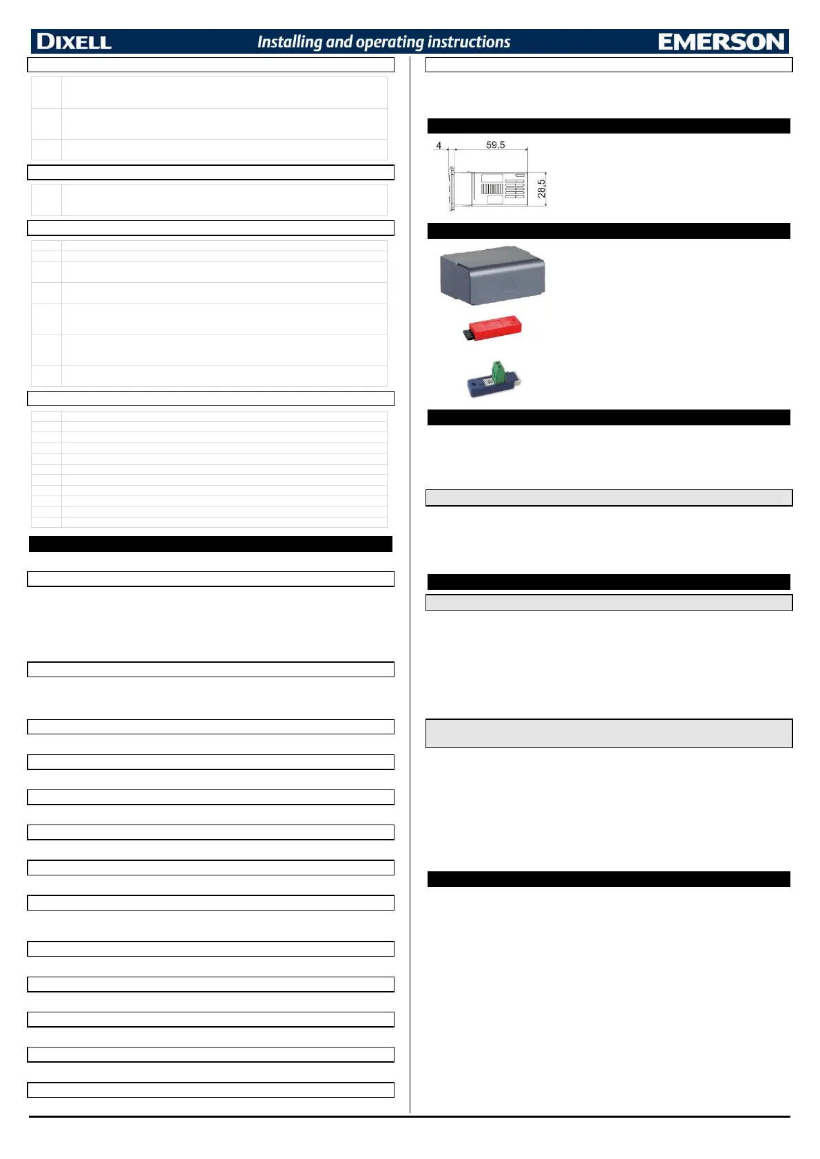
14 INSTALLATION AND MOUNTING
Instrument XR70CHC shall be mounted on vertical panel, in a
29x71 mm hole, and fixed using the special bracket supplied.
The temperature range allowed for correct operation is 0 to 60°C.
Avoid places subject to strong vibrations, corrosive gases,
excessive dirt or humidity. The same recommendations apply to
probes. Let air circulate by the cooling holes.
The MDP/CX rear cover can be used to increase the protection
from water and dust.
The HOT-KEY is used for a quick and easy upload (from device
to HOT-KEY) or download (from HOT-KEY to device) the
parameter map.
The XJ485LE serial interface converts the TTL output into an
RS485 signal that can be used to connect the unit to the
controlling and supervising system. Please note that other
version of this converter does not work with XR-CHC devices.
16 ELECTRICAL CONNECTIONS
The instrument is provided with screw terminal block to connect cables with a cross section up to
2.5mm
2
. Before connecting cables make sure the power supply complies with the instrument’s
requirements. Separate the probe cables from the power supply cables, from the outputs and the
power connections. Do not exceed the maximum current allowed on each relay, in case of heavier
loads use a suitable external relay.
16.1 PROBES
The probes shall be mounted with the bulb upwards to prevent damages due to casual liquid
infiltration. It is recommended to place the thermostat probe away from air streams to correctly
measure the average room temperature. Place the defrost termination probe among the evaporator
fins in the coldest place, where most ice is formed, far from heaters or from the warmest place during
defrost, to prevent premature defrost termination.
17 USE THE HOT-KEY
17.1 SAVE PARAMETERS IN A HOT-KEY (UPLOAD FROM INSTRUMENT)
1. Program one controller with the front keypad.
2. When the controller is ON, insert the “HOT-KEY” and push UP button; the “UP” message
appears followed a by flashing “End”
3. Push “SET” key and the “End” will stop flashing.
4. Turn OFF the instrument and then remove the “HOT-KEY”. At the end turn the instrument ON
again.
NOTE: the “Err” message appears in case of a failed programming operation. In this case push again
the UP button if you want to restart the upload again or remove the “HOT-KEY” to abort the operation.
17.2 COPY PARAMETERS FROM A HOT-KEY (DOWNLOAD PARAMETER
VALUES)
1. Turn OFF the instrument.
2. Insert a programmed “HOT-KEY” into the 5-PIN port and then turn the Controller ON.
3. The parameter list of the “HOT-KEY” is automatically copied into the controller memory. During
this operation the “do” message will blink
4. A flashing “End” label will inform that the operation was successful
5. Remove the “HOT-KEY”.
6. After some seconds the instrument will restart, using with the new parameters.
NOTE: the message “Err” is displayed for failed programming. In this case turn the unit off and then on
if you want to restart the download again or remove the “HOT-KEY” to abort the operation.
18 INTERNAL MEMORY
The controller has an internal memory where are stored:
- Two different parameter maps identified as C1 and C2
- Factory default configurations for both C1 and C2 parameters map
The controller is always shipped with:
- Parameter map C1 = factory default configuration C1
- Parameter map C2= factory default configuration C2
Any modification to parameter map C1 or C2 does not change the default factory values.
It is possible to change parameter map between C1 and C2 by using a digital input or a button properly
configurated (ixF or LG2=CC).
It is possible to restore factory defaults values for both C1 or C2 parameters map by using UP2=LdC (Load
default configuration) function.
NOTES:
- If controller is using C1 parameter map, the factory default configuration C1 will be reloaded
overwriting C1 parameter map. The same for parameter map C2.
- The factory default configurations are read only (it is not possible to modify them on the field).

 Loading...