10 • XR75CX I&O Manual 026-1210 Rev 4
FnC Fans operating mode
(C-n; o-n; C-Y; o-Y) C-n = runs with the compressor, OFF
during defrost; o-n = continuous mode, OFF during defrost; C-
Y = runs with the compressor, ON during defrost; o-Y =
continuous mode, ON during defrost.
Fnd Fans delay after defrost
(0 to 255min) Interval between end of defrost and evaporator
fans start.
Fct
Temperature differential to avoid fan
short cycles
(0 to 59°C; 0 to 90°F) (N.B.: if Fct=0 function disabled) If the
difference of temperature between the evaporator and the room
probes is higher than Fct value, the fans will be switched ON.
FSt Fans stop temperature
(-50 to 50°C; -58 to 122°F) Setting of temperature, detected by
evaporator probe, above which fans are always OFF.
Fon Fan ON time
(0 to 15min) With FnC=C_n or C_Y, (fan activated in parallel
with compressor) it sets the evaporator fan ON cycling time
when the compressor is OFF. With Fon=0 and FoF≠0 the fan
are always OFF, with Fon=0 and FoF=0 the fan are always
OFF.
FoF Fan OFF time
(0 to 15min)
With FnC=C_n or C_Y, (fan activated in parallel with
compressor) it sets the evaporator fan OFF cycling time when
the compressor is OFF.
With Fon=0 and FoF≠0 the fan are always OFF, with Fon=0
and FoF=0 the fan are always OFF.
FAP Probe selection for fan management
(nP; P1; P2; P3; P4) nP = no probe; P1 =thermostat probe; P2 =
evaporator probe; P3 =configurable probe; P4 = Probe on Hot
Key plug.
AUXILIARY THERMOSTAT CONFIGURATION (terms. 1-2) - oA2 = AUS
ACH Kind of regulation for auxiliary relay (Ht; CL) Ht = heating; CL = cooling
SAA Set Point for auxiliary relay
(-50 to 110.0°C; -58 to 230°F) It defines the room temperature
setpoint to switch auxiliary relay.
SHY Differential for auxiliary output
(0.1 to 25.5°C; 1 to 45°F) Intervention differential for auxiliary
output setpoint.
ACH=CL, AUX Cut in is [SAA+SHY]; AUX Cut out is SAA.
ACH=Ht, AUX Cut in is [SAA–SHY]; AUX Cut out is SAA.
ArP Probe selection for auxiliary
(nP; P1; P2; P3; P4) nP = no probe, the auxiliary relay is
switched only by the digital input; P1 = Probe 1 (Thermostat
probe); P2 = Probe 2 (evaporator probe); P3 = Probe 3 (display
probe); P4 = Probe 4
Sdd Auxiliary relay OFF during defrost
(n; Y) n = the auxiliary relay operates during defrost; Y = the
auxiliary relay is switched OFF during defrost
ALARMS
ALP Probe selection for alarm
(nP; P1; P2; P3; P4) nP = no probe, the temperature alarms are
disabled; P1 = Probe 1 (Thermostat probe); P2 = Probe 2
(evaporator probe); P3 = Probe 3 (display probe); P4 = Fourth
probe
ALC Temperature alarms configuration
(Ab; rE) Ab = absolute temperature, alarm temperature is given
by the ALL or ALU values. rE = temperature alarms are
referred to the setpoint. Temperature alarm is enabled when the
temperature exceeds the [SET+ALU] or [SET-ALL] values.
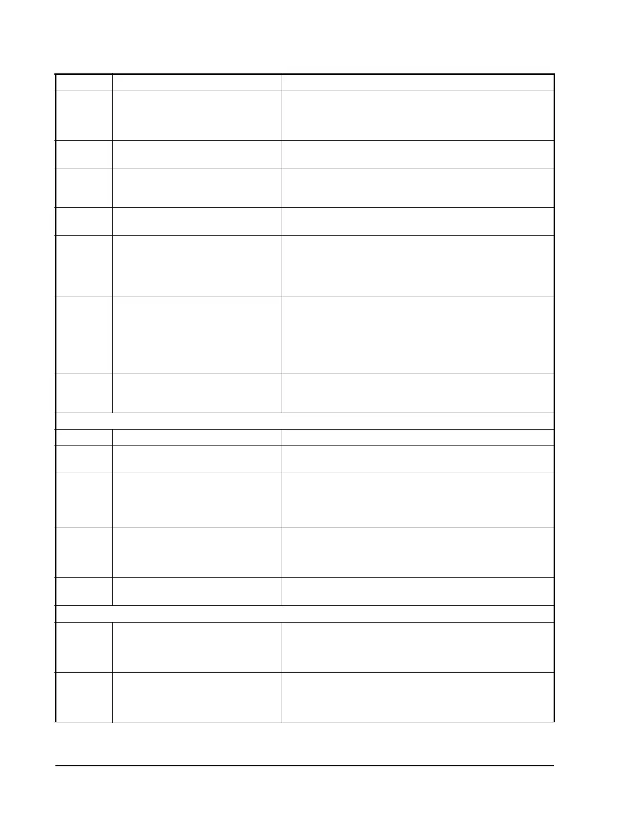
Code Parameter Function
Table 7-1 - List of Parameters

 Loading...