D-Series with FF Option Installation, Operation & Maintenance
502.969.8000
2
Introduction
This manual is intended to provide instruction for Installing, Operating and Maintaining the TopWorx Model
DXP/DXS-FF Discrete Valve Controller with FOUNDATION™ Fieldbus.
Warnings and Precautions that require special instructions or
considerations are noted by this symbol.
DXP Quick Start Installation Guide
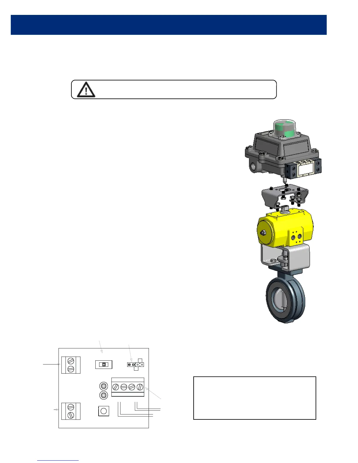
Step 1 - Mount DXP/DXS-FF (Fig. 1)
a) Connect bolts firmly between switchbox and bracket
b) Connect bolts loosely between actuator and bracket
c) Cycle actuator to limits in both directions 3 times to center shaft
d) Tighten the bolts between the actuator and bracket
Step 2 - Secure pneumatic connections
a) Refer to Figure 2 for details
b) Use of Locktite 567 is recommended
Step 3 - Make electrical connections
a) Attach fieldbus wiring to FF terminals (Fig. 2)
b) F
OUNDATION Fieldbus wiring is polarity insensitive
Step 4 - Calibrate switches
a) Move the valve to the CLOSE position, push and rotate lower
cam to activate the Red LED
b) Move the valve to the OPEN position, push and rotate upper
cam to activate the Green LED
c) Verify calibration by actuating valve open and closed several times
NOTE: Switches can be set using calibration switch without FF connection by
using any 9-32VDC power source.
Step 5 - Commission DXP-FF
a) Connect single DO to Channel 5
• No DI needed - Readback_D provides the actual valve position
b) Set the Mode to AUTO (Automatic) in the Transducer Block
Mounting - Figure 1
FLASH RESET
CLOSE
FF
AUX
OPEN
- V2 +
- V1 +
Wrt Prt
FF
Si m
SCM-FF
Calibration Switch
Auxilliary Input
Termi nals
(Dry contacts only)
Foundation
Fieldbus Loop
Termi nals
Piezo Pilot
Terminals
Single Pilot
Dual Pilot
Std Operation
Jumper Location
+ = Orange
- = Black
NOTE: TopWorx has pre-configured
modules and faceplates available for
DeltaV control systems. Contact
TopWorx factory for more
information.
Wiring - Figure 2