1-3-1 SFTY_Z13N
STANDARD NOTES FOR SERVICING
Circuit Board Indications
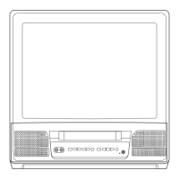
1. The output pin of the 3 pin Regulator ICs is indi-
cated as shown:
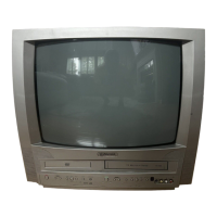
2. For other ICs, pin 1 and every 5th pin is indicated
as shown:
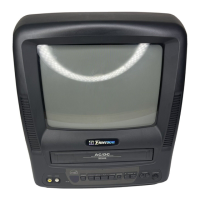
3. The 1st pin of every pin connector are indicated as
shown:
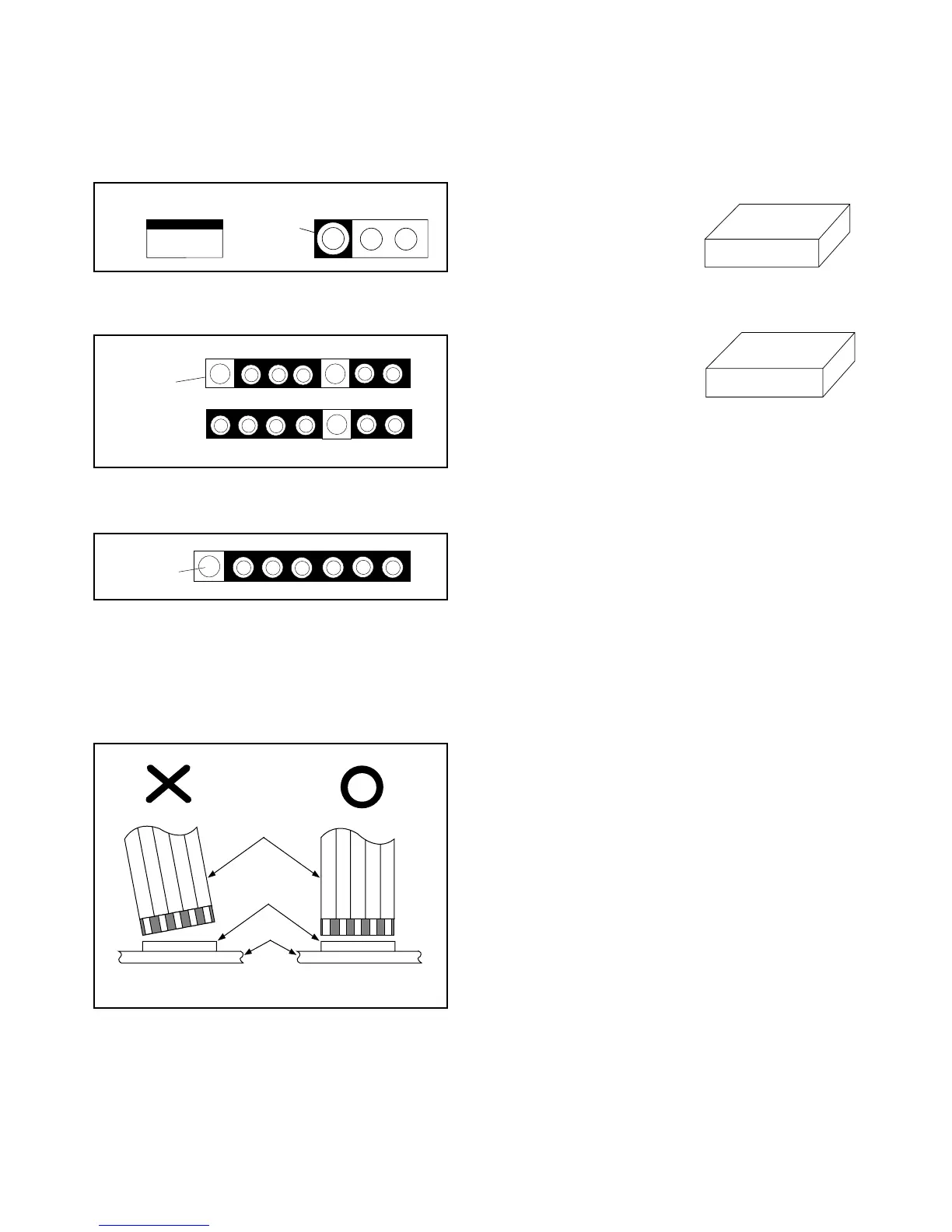
Instructions for Connectors
1. When you connect or disconnect FFC cable (con-
nector), be sure to disconnect the AC cord.
2. FFC cable (connector) should be inserted parallel
into the connector, not at an angle.
[ CBA= Circuit Board Assembly ]
How to Read the Values of the Rect-
angular Type Chip Components
Example:
(a) Resistor
(b) Capacitor
Caution:
Once chip parts (Resistors, Capacitors, Transistors,
etc.) are removed, they must not be reused. Always
use a new part.
Pb Free Solder (PbF)
When soldering, be sure to use the Pb free solder.
Replacement Procedures for
Leadless (Chip) Components
The Following Procedures are Recom-
mended for the Replacement of the Lead-
less Components Used in this Unit.
1. Preparation for replacement
a. Soldering Iron
Use a pencil-type soldering iron (less than 30
watts).
b. Solder
Eutectic solder (Tin 63%, Lead 37%) is recom-
mended.
c. Soldering time
Do not apply heat for more than 4 seconds.
d. Preheating
Leadless capacitor must be preheated before
installation. (130°C~150°C, for about two minutes.)
Notes:
a. Leadless components must not be reused after
removal.
b. Excessive mechanical stress and rubbing for the
component electrode must be avoided.
Top View
Out
In
Bottom View
Input
5
10
Pin 1
Pin 1
FFC Cable
Connector
CBA
* Be careful to avoid a short circuit.
(Top View)
473
= 473 = 47 [k
Ω
]
(Top View)
= Not Shown

 Loading...