Site Considerations for Equipment Installation, Grounding, and Wiring Manual
D301452X012
September 2019
Grounding and Isolation 13
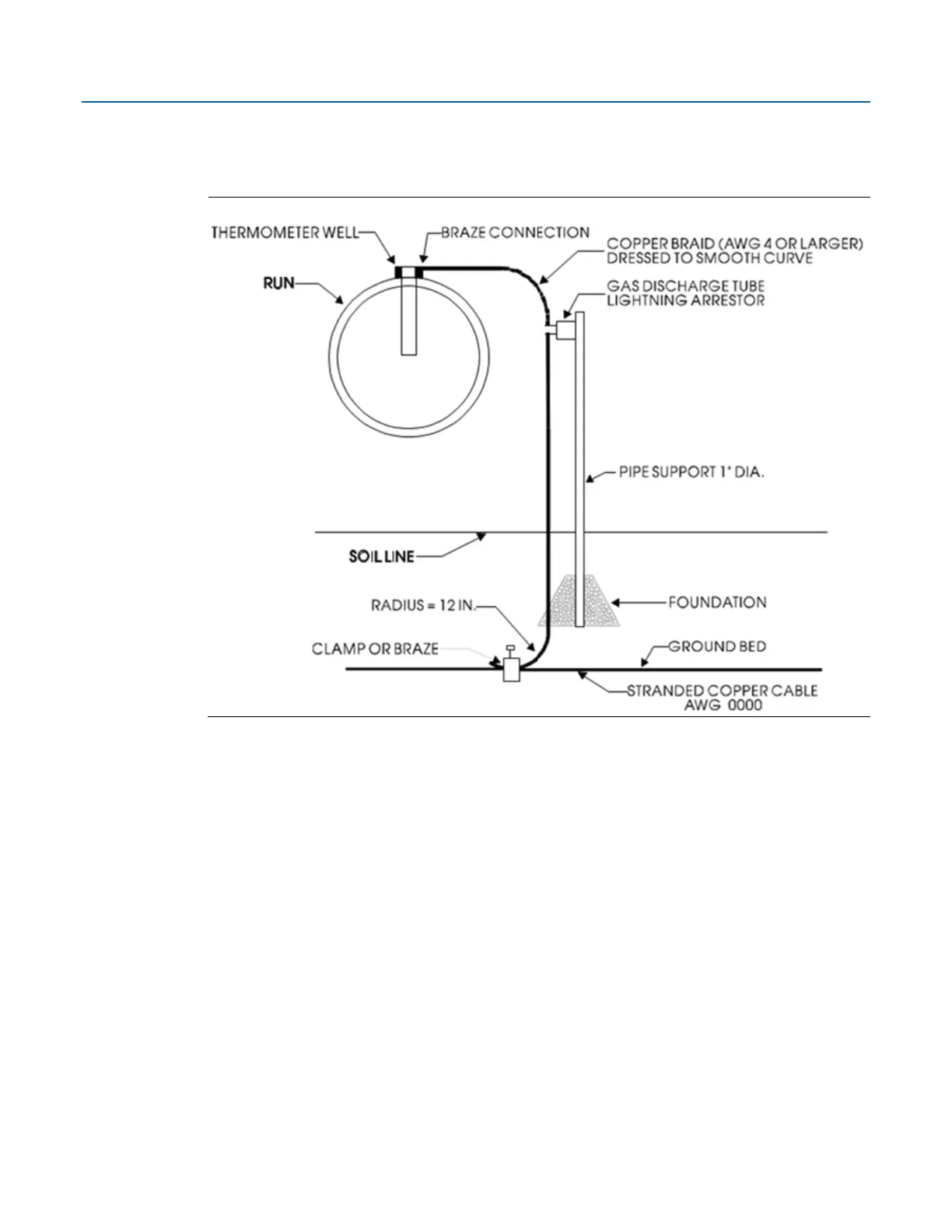
Gas lines also require special grounding considerations. If a gas meter run includes a thermocouple
or RTD sensor installed in a thermowell, connect the well (not the sensor) to a gas discharge-type
lightning arrester as shown in Figure 3-7.
Figure 3-7: Grounding of Thermometer Well in Gas Line
Dress a copper braid, brazed to the thermal well, into a smooth curve and connect it to the arrester
as shown. The curve is necessary to minimize arcing caused by lightning strikes or high static
surges. The path from the lightning arrester to the ground bed should also be smooth and free
from sharp bends for the same reason.
3.4 Isolating Equipment from the Pipeline
3.4.1 Meter Runs without Cathodic Protection
Some (but not all) flow computers may be mounted directly on the pipeline. For example, you can
mount the FB1100 andFB1200 flow computers directly on a pipeline using the traditional
mounting kit or a coplanar mounting kit, but only if the pipeline includes a process manifold. If
direct mount is not allowed or supported (as with the FB2100 and FB2200 flow computers), mount
the flow computers remotely on a vertical standalone two-inch pipe (see Figure 3-8). Run the earth
ground cable between the flow computer’s ground lug and earth ground (rod or bed) even though
the flow computer’s multivariable transducer may be grounded to the pipeline. If any pressure
transmitters or pulse transducers are remotely mounted, connect their chassis grounds to the
pipeline or earth ground.