Type 310A
9
Install the Type 310A-32A-32A into the pipeline using
adequate gaskets for anged regulator units and good
piping technique. Be sure to provide suitable pressure
gauges where appropriate, block valves, bypass
valves and piping, and bleed valves to permit safe
and easy maintenance of both the working monitor
regulator and the second-stage working regulator. Be
sure ow will be in the direction indicated by the arrow
cast on the body.
Refer to the Figure 8 schematic and Figure 14, and
proceed in the following steps.
1. Attach the intermediate pressure control line
(1/2 NPT pipe) between the 1/2 NPT pipe tee
(key 72, Figure 14) and the intermediate pressure
portion of the downstream piping. Install hand
valve B in this line.
2. Connect 1/2 NPT distribution pressure control
line piping between the 1/2 NPT connection
in the mounting bracket (key 45, Figure 14) and
the pipeline downstream of the second-stage
working regulator. Include hand valve A in this
control line.
3. Pipe the pilot supply line to 1/4 NPT connection in
the back of the working pilot body. Supply pressure
should be ltered if excess dirt or condensate is
present in the supply gas.
4. Install downstream working regulator per guidelines.
Startup
1. Before introducing any pressure to the unit,
close hand valve A in the distribution pressure
control line and hand valve B in the intermediate
pressure control line.
2. Slowly open the hand valve in the pilot supply line.
3. Slowly open the upstream block valve and partially
open the downstream block valve for minimum ow.
4. Slowly open hand valve B and allow the
intermediate pressure to increase to the
working pilot setting.
5. Put the second-stage working regulator into
operation according to recommended procedures
and instructions furnished with the second-stage
working regulator.
6. After the distribution pressure has been established
slowly open hand valve A.
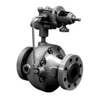
Figure 8. Typical Working Monitor Installation
A0714_2
 Loading...