Instruction Manual
D101550X012
8532 Valve
June 2017
6
Table 4. Valve Body Data, CL300
VALVE SIZE,
NPS
SHAFT DIA. AT
YOKE BEARING
FACE‐TO‐FACE DIMENSION
(1)
MINIMUM
I.D
.(2)
APPROXIMATE WEIGHT, KILOGRAMS
Wafer and
Lugged
Double-Flange
mm Wafer Lugged Double-Flange
14 44.45 117.5 290 304.3 125.2 231.3 345
16 44.45 133.4 310 346.2 189.2 300.7 563
18 57.15 149.2 330 389.4 237.7 411.4 591
20 69.9 155.6 350 442.0 370.6 551.1 706
24 69.9 181.0 390 523.2 477.2 828.7 1307
VALVE SIZE,
NPS
SHAFT DIA. AT
YOKE BEARING
FACE‐TO‐FACE DIMENSION
(1)
MINIMUM
I.D
.(2)
APPROXIMATE WEIGHT, POUNDS
Wafer and
Lugged
Double-Flange
Inches Wafer Lugged Double-Flange
14 1‐3/4 4.625 11.41 11.98 276 510 760
16 1‐3/4 5.25 12.20 13.63 417 663 1240
18 2‐1/4 5.875 13.00 15.32 524 907 1303
20 2‐3/4 6.125 13.78 17.40 817 1215 4556
24 2‐3/4 7.125 15.35 20.59 1052 1827 2881
1. Face‐to‐face dimensions are in compliance with MSS SP68 and API 609 specifications.
2. Minimum I.D. is the minimum pipe or flange I.D. required for disk swing clearance. Applies to wafer and lugged valve bodies only.
CAUTION
When using an actuator, the actuator travel stop (or actuator travel, for actuators without adjustable stops) must be
adjusted so the disk stop in the valve does not absorb the output of the actuator. Failure to limit the actuator travel as
described in the Adjusting the Actuator Travel Stops or Travel steps can result in damage to the valve, shaft(s), or other
valve components.
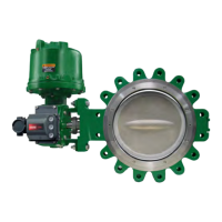
An 8532 valve is normally shipped as part of an assembly with an actuator and other accessories such as a valve
positioner. If the valve and actuator have been purchased separately or if the actuator has been removed for
maintenance, properly mount the actuator and adjust valve/actuator travel and all travel stops before inserting the
valve into the line.
CAUTION
Damage to the disk will occur if any pipe flanges or piping connected to the valve interfere with the disk rotation path. Be
certain to align the valve accurately to avoid contact between the disk (key 2) and the flanges.

 Loading...