Instruction Manual
D101550X012
8532 Valve
June 2017
5
Valve Orientation
The valve can be installed in any orientation, however it is recommended that the valve drive shaft be horizontal and
the actuator vertical as shown in figure 4.
Install the valve with the high‐pressure shutoff side in the direction noted by the flow arrow for proper installation, and
see figure 4 for more information.
Before Installing the Valve
WARNING
The edges of a rotating valve disk (key 2, figure 9 or 10) close with a shearing, cutting motion. To avoid personal injury,
keep hands, tools, and other objects away from the disk while stroking the valve.
If the 8532 valve is equipped with a fail‐open actuator, cycle the valve into the fully closed position. Ensure the valve cannot
open during installation by using travel stops, a manual actuator, a constant supply pressure to the pneumatic actuator, or
other steps as necessary.
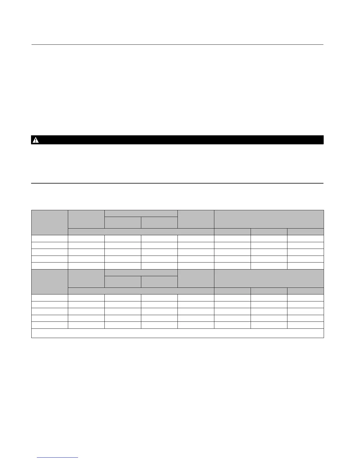
Table 3. Valve Body Data, CL150
VALVE SIZE,
NPS
SHAFT DIA. AT
YOKE BEARING
FACE‐TO‐FACE DIMENSION
(1)
MINIMUM
I.D
.(2)
APPROXIMATE WEIGHT, KILOGRAMS
Wafer and
Lugged
Double-Flange
mm Wafer Lugged Double-Flange
14 30.2 92.1 191 331.2 71.7 94.8 152
16 31.75 101.6 216 375.2 93.9 137.9 201
18 38.1 114.3 222 418.8 139.3 178.3 243
20 44.45 127.0 229 464.1 166.9 223.6 277
24 57.15 154.0 267 580.9 255.4 350.6 434
VALVE SIZE,
NPS
SHAFT DIA. AT
YOKE BEARING
FACE‐TO‐FACE DIMENSION
(1)
MINIMUM
I.D
.(2)
APPROXIMATE WEIGHT, POUNDS
Wafer and
Lugged
Double-Flange
Inches Wafer Lugged Double-Flange
14 1‐3/16 3.625 7.50 13.04 158 209 335
16 1‐1/4 4 8.50 14.77 207 304 443
18 1/2 4.5 8.75 16.49 307 393 535
20 1‐3/4 5 9.00 18.27 368 493 611
24 2‐1/4 6.0625 10.50 22.87 563 773 956
1. Face‐to‐face dimensions are in compliance with MSS SP68 and API 609 specifications.
2. Minimum I.D. is the minimum pipe or flange I.D. required for disk swing clearance. Applies to wafer and lugged valve bodies only.

 Loading...


