EDR and ETR Valves
Instruction Manual
Form 5050
August 2006
8
PACKING
BOX
NOTE:
REFER TO FIGURE 5 OR 6 FOR PACKING ARRANGEMENTS.
1
1
10A6681-A / DOC
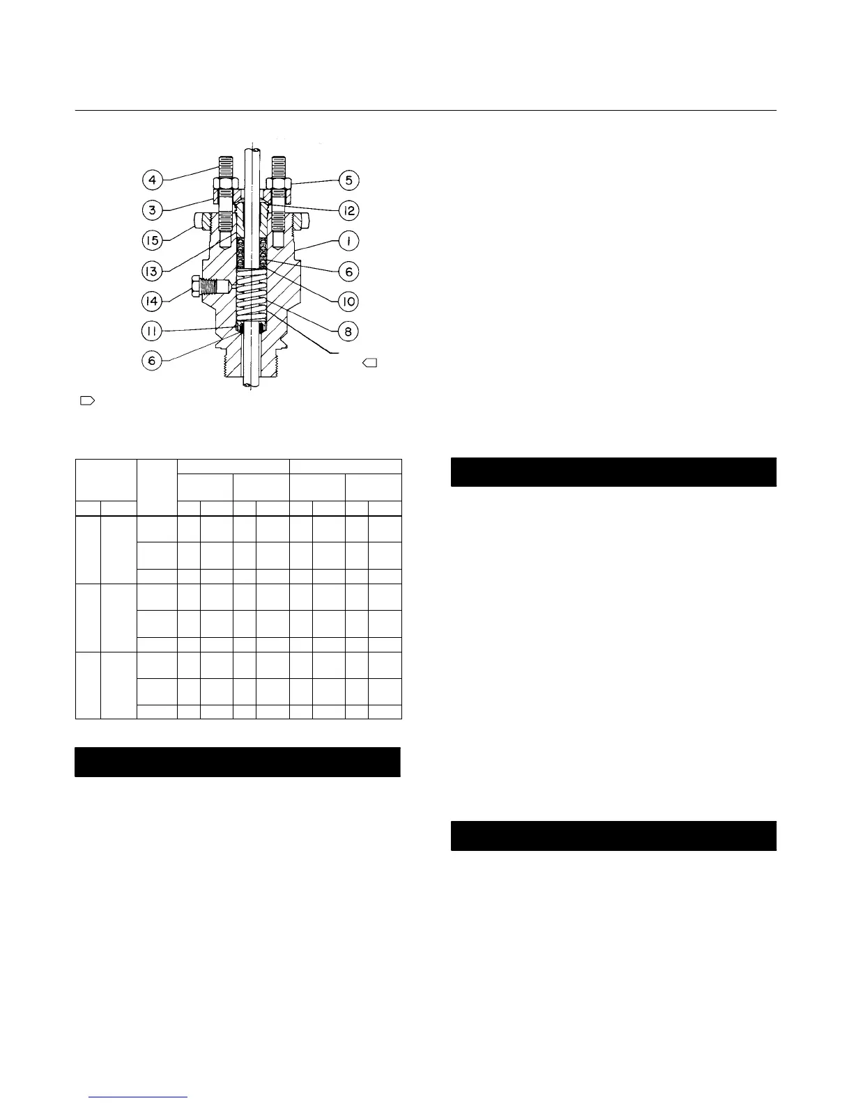
Figure 4. Bonnet Assembly
Table 4. Recommended Torque for Packing Flange Nuts
VALVE
STEM
DIAMETER
CLASS
GRAPHITE PACKING PTFE PACKING
Minimum
Torque
Maximum
Torque
Minimum
Torque
Maximum
Torque
mm Inches
NSm LbfSin NSm LbfSin NSm LbfSin NSm LbfSin
9.5 3/8
125,
150
3 24 5 48 1 12 3 24
250,
300
4 36 7 60 2 18 3 30
600 5 48 8 72 3 24 4 36
12.7 1/2
125,
150
5 48 8 72 3 24 4 36
250,
300
7 60 10 84 3 30 5 42
600 10 84 14 120 5 42 7 60
19.1 3/4
125,
150
11 96 16 144 5 48 8 72
250,
300
14 120 20 180 7 60 10 90
600 20 180 30 264 10 90 15 132
CAUTION
To prevent possible product damage,
avoid scratching the packing box walls
when removing old packing parts. Also
inspect valve stem threads and
packing box surfaces for sharp edges
which may damage packing.
6. Avoid scratching the packing box walls when
removing the old packing parts. Clean the packing
box (see figure 4), and clean, inspect, or replace
metal packing parts. Generally, the metal packing
parts are not part of the packing kits listed in the
Parts List section, and they must be ordered
individually.
7. Inspect the valve stem threads and packing box
surfaces for any sharp edges which might cut the
packing. Scratches or burrs on the stem surfaces
can cause packing box leakage or damage to new
packing. If the surface condition cannot be improved
by light sanding, replace the damaged parts by
following the appropriate steps in the Trim
Maintenance procedure.
Note
If the control valve assembly was
purchased for an application where the
service temperatures are under 232_C
(450_F), the bonnet may be unscrewed
from the valve body. Where
temperatures are greater than 232_C
(450_F), the bonnet is seal welded to
the valve body.
CAUTION
To prevent possible product damage,
set the bonnet on a protective surface
in the following procedure.
8. If necessary, remove the bonnet assembly from
the valve by unscrewing it. Some applications
require seal welding the bonnet to the valve body,
and the bonnet should not be removed. Set the
bonnet on a protective surface to prevent damage to
the bonnet gasket surface.
Installing Packing
If the trim is removed, refer to Trim Maintenance
procedures, and install the trim (including the valve
stem) before installing the packing. If necessary, use
the Lapping Metal Seats procedures before installing
packing. Key number locations are shown in figure 5
or 6 unless otherwise indicated.
CAUTION
To prevent possible product damage,
take care when installing the bonnet
over the valve stem in the following
procedure.
1. If the bonnet has been removed from the valve
body, install the replacement bonnet (see figure 4).
Carefully slide the bonnet over the valve stem
without damaging the stem surfaces.

 Loading...


