Instruction Manual
D103175X012
GX Valve and Actuator
April 2011
24
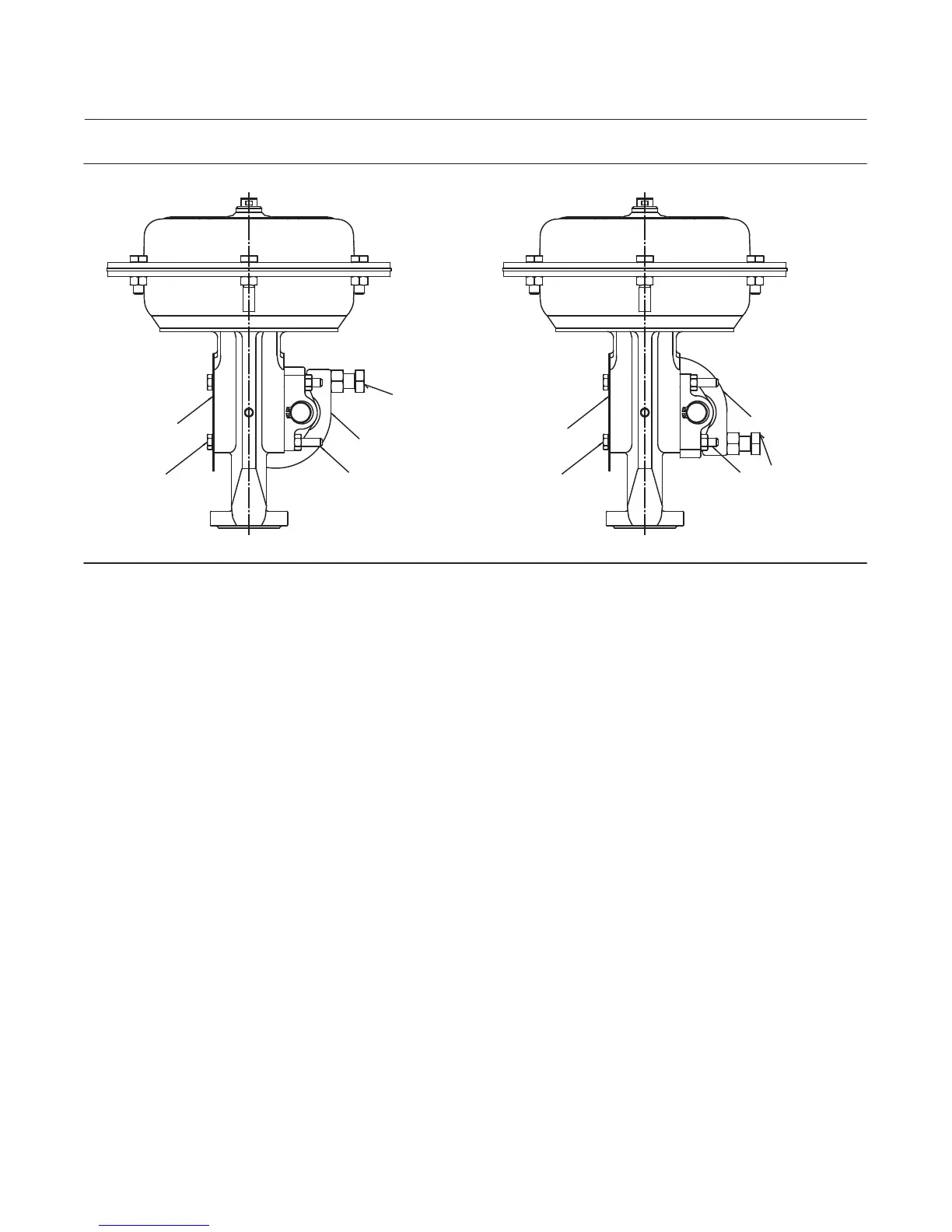
Figure 8. Fisher GX Travel Stop Assembly
COVER PLATE
COVER PLATE
CAP SCREW
(4)
CAP SCREW (4)
LEVER
LEVER
ADJUSTABLE
CAP SCREW (2)
ADJUSTABLE
CAP SCREW (2)
STUD AND
NUT (4)
STUD AND
NUT (4)
DOWNSTOP
UPSTOP
GX Travel Stop Installation
Downstop
1. Note the orientation of the lever to the stem connector for downstop positioning, as shown in figure 9. Adjust the
travel stop to allow positioning the lever below the stem connector before installation.
2. Install the travel stop to the GX mounting pad with four studs and nuts, as shown in figure 8. Torque to 24.5 NSm
(18 lbfSft).
3. Apply lithium grease to the tip of the lever (where it contacts the stem connector) and to the two adjustable cap
screws, as shown in figure 9.
Upstop
1. Note the orientation of the lever to the stem connector for upstop positioning, as shown in figure 9. Adjust the
travel stop to allow positioning the lever above the stem connector before installation.
2. Install the travel stop to the GX mounting pad with four studs and nuts, as shown in figure 8. Torque to 24.5 NSm
(18 lbfSft).
3. Apply lithium grease to the tip of the lever (where it contacts the stem connector) and to the two adjustable cap
screws, as shown in figure 9.

 Loading...


