Instruction Manual
D103175X012
GX Valve and Actuator
April 2011
6
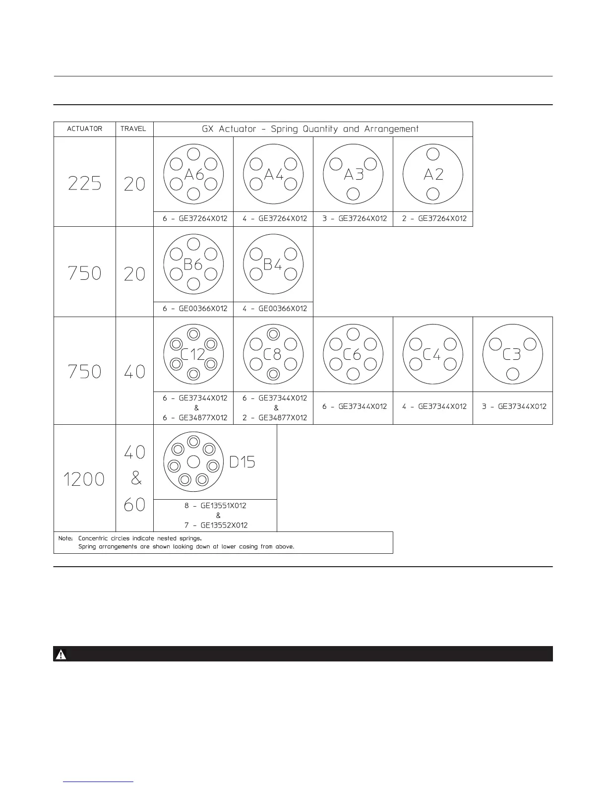
Figure 3. Spring Configuration
Actuator Disassembly (For Air‐to‐Close Constructions ‐ see figure 20 or 21)
1. Remove the stem connector nut half (key 23), stem connector bolt half (key 24), and travel indicator (key 26).
WARNING
To avoid personal injury or property damage due to actuator springs (key 12) being under compression, remove the long
cap screws (key 16) last.
The upper actuator casing may remain fixed to the diaphragm and lower casing during disassembly, even if the casing cap
screws have been loosened. If this happens, the actuator springs are still under compression. The upper casing could

 Loading...


