Instruction Manual
D103553X012
Large ET and ED Valves
July 2017
16
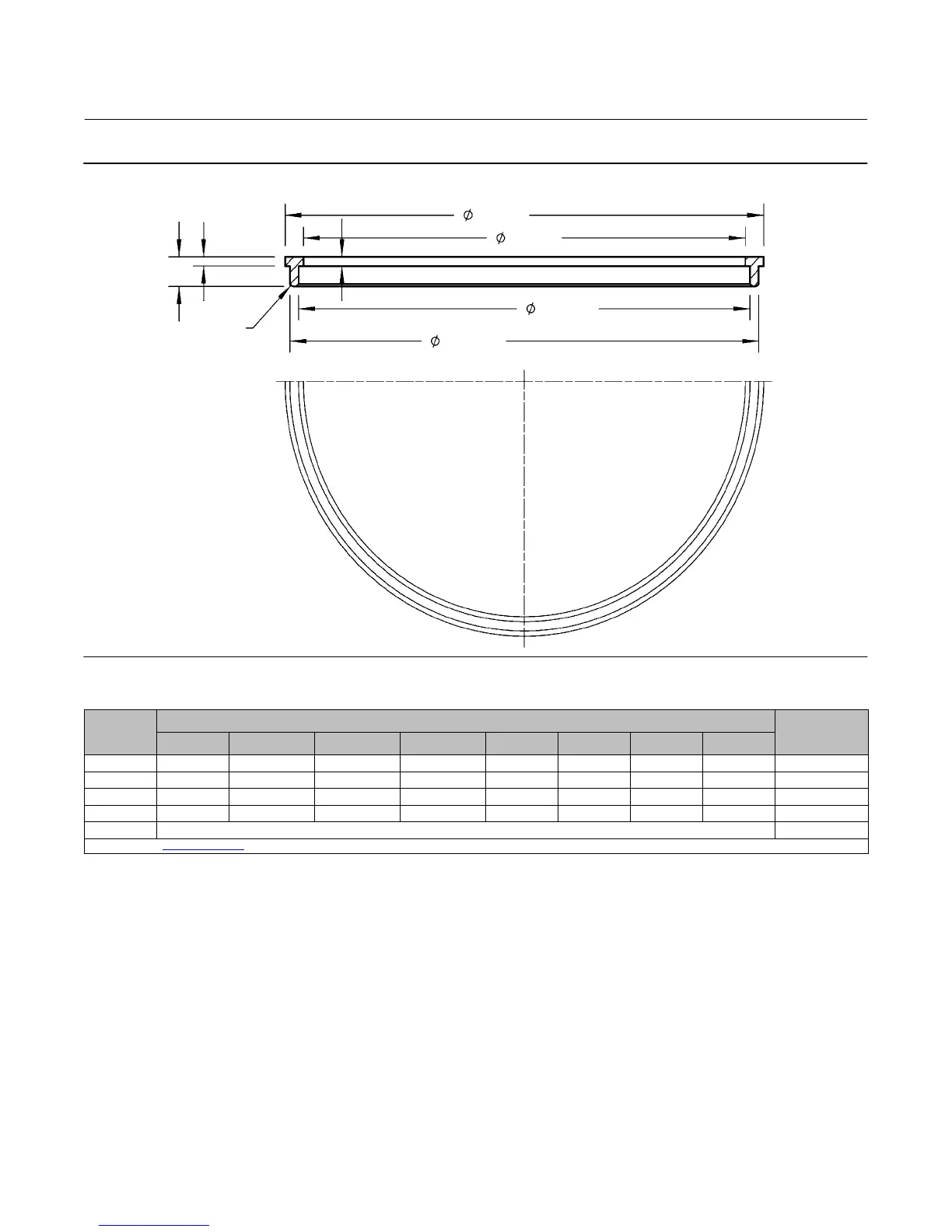
Figure 4. Bore Seal Installation Tool
GE22109-A
A
B
C
D
E
F
G
H
Table 5. Bore Seal Installation Tool Dimensions
VALVE
PORT SIZE,
INCH
Dimensions, Inches (See Figure 4)
Tool Part
Number
A B C D E F G H
10.00 10.12 9.7 9.80-9.82 10.00-10.02 0.10 0.10 0.32 R.06 GE17914X012
11.00 12.59 12.17 12.27-12.29 12.49-12.47 0.10 0.10 0.32 R.07 GE18183X012
14.75 14.84 14.424-14.416 14.516-14.536 14.736-14.716 0.10 0.10 0.32 R.05 GE34073X012
18.25 18.35 17.925-17.935 18.030-18.050 18.230-18.250 0.10 0.10 0.32 R.06 GG43649X012
24.00
(1) (1)
1. Contact your Emerson sales office or Local Business Partner for this tool and dimensions.
For ET/EWT Valves
1. Carefully pry or cut out the seat ring seal ring (key 223) from its groove in the seat ring (key 9). Discard the old seat
ring seal ring.
2. Then inspect the seat ring (key 9) for nicks, scratches, or other damage that would prevent proper operation of the
valve. Replace the seat ring if necessary. A replacement seat ring is available individually (key 9 only) or as a seat ring
and cage assembly (key 9 and 3). If replacing individually proceed to step 3, otherwise proceed directly to step 7.
3. Make sure the bolts or cap screws that were installed in the seat ring during the Disassembly procedure are still
installed.
4. Orient the cage (key 3) and seat ring so that the threads on each are facing one another for assembly. The bottom
of the cage should be facing the top of the seat ring.
5. Using a pry bar to pry against the bolts or cap screws, turn the seat ring clockwise into the cage until tight.
Afterwords remove the two bolts or cap screws.

 Loading...


