Instruction Manual
D103302X012
A81 Valve
January 2011
3
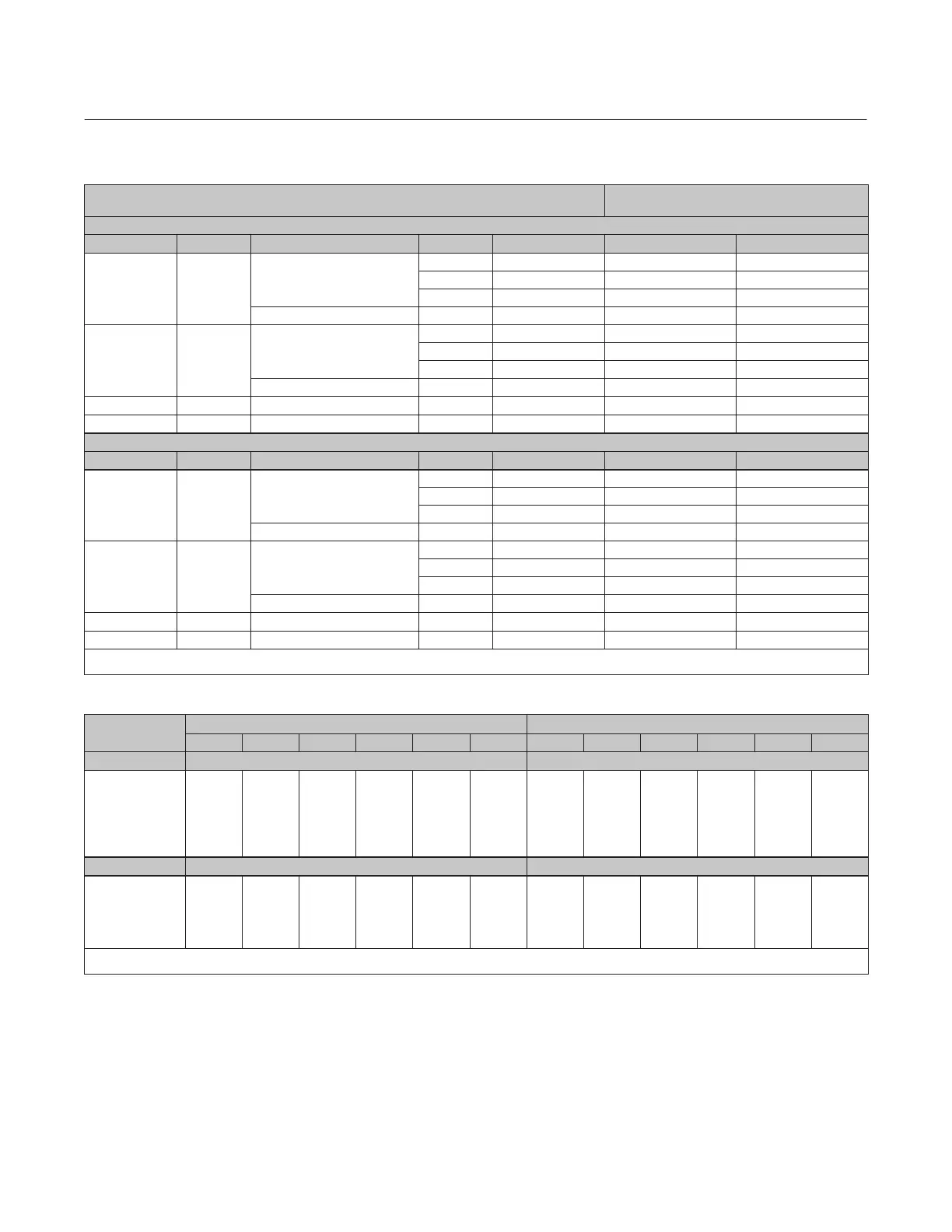
Table 3. Material Temperature Capabilities
MATERIAL TEMPERATURE
LIMITS
(1)
EN Materials
Valve Body Shaft Bearing Lining and Jacket Seal Packing _C _F
1.0619 Steel S17400 or
S20910
PEEK / PTFE
PTFE PTFE or Graphite –10 to 232 14 to 450
UHMWPE PTFE or Graphite –10 to 93 14 to 200
Metal PTFE or Graphite –10 to 232 14 to 450
R30006 (Alloy 6) Metal Graphite –10 to 400
(2)
14 to 752
(2)
1.4409
Stainless Steel
S20910 PEEK / PTFE
PTFE PTFE or Graphite –10 to 232 14 to 450
UHMWPE PTFE or Graphite –10 to 93 14 to 200
Metal PTFE or Graphite –10 to 232 14 to 450
R30006 (Alloy 6) Metal Graphite –10 to 500
(2)
14 to 932
(2)
CW2M N10276 PEEK / PTFE PTFE PTFE –10 to 232 14 to 450
M35‐2 N05500 PEEK / PTFE PTFE PTFE –10 to 232 14 to 450
ASME Materials
Valve Body Shaft Bearing Lining and Jacket Seal Packing _C _F
WCC steel S17400 or
S20910
PEEK / PTFE
PTFE PTFE or Graphite –29 to 232 -20 to 450
UHMWPE PTFE or Graphite –18 to 93 0 to 200
Metal PTFE or Graphite –29 to 232 -20 to 450
R30006 (Alloy 6) Metal Graphite –29 to 427
(2)
-20 to 800
(2)
CF3M Stainless
Steel
S20910 PEEK / PTFE
PTFE PTFE or Graphite –46 to 232 –50 to 450
UHMWPE PTFE or Graphite –18 to 93 0 to 200
Metal PTFE or Graphite –129 to 232 –200 to 450
R30006 (Alloy 6) Metal Graphite –129 to 454
(2)
–200 to 850
(2)
CW2M N10276 PEEK / PTFE PTFE PTFE –46 to 232 –50 to 450
M35‐2 N05500 PEEK / PTFE PTFE PTFE –46 to 232 –50 to 450
1. Minimum allowable temperature for PN series flanges is -10_C (14_F). See requirements of EN 13445‐2 Annex B for applications below -10_C (14_F) with PN series flanges.
2. For applications exceeding 316_C (600_F), consult your Emerson Process Management sales office for appropriate disk material selection.
Table 4. Maximum Allowable Inlet Pressure for CW2M and M35‐2 Valves
TEMPERATURE
CW2M
(1)
M35‐2
(1)
150
(2)
300
(2)
PN 10
(2)
PN 16
(2)
PN 25
(2)
PN 40
(2)
150
(2)
300
(2)
PN 10
(2)
PN 16
(2)
PN 25
(2)
PN 40
(2)
_C Bar Bar
–46 to 38
50
100
150
200
232
20.0
19.5
17.7
15.8
13.8
12.7
51.7
51.7
51.5
50.3
48.3
47.0
10.0
9.9
9.4
9.4
9.1
9.1
16.0
15.9
15.1
15.1
14.6
14.6
25.0
24.8
23.6
23.6
22.9
22.9
40.0
39.6
37.8
37.8
36.6
36.6
18.3
18.2
17.7
15.8
14.0
12.8
47.9
47.9
47.8
47.2
45.6
45.5
9.3
9.3
9.3
9.3
9.0
9.0
15.2
15.2
15.1
14.8
14.5
14.5
23.8
23.8
23.7
23.4
22.5
22.4
37.9
37.9
37.8
37.2
36.3
36.2
_F Psig Psig
–50 to 100
200
300
400
450
290
260
230
200
185
750
750
730
700
680
145
144
137
133
133
232
230
219
212
212
362
359
342
331
331
580
575
548
530
530
265
260
230
200
185
695
695
685
660
660
135
135
135
130
130
220
220
215
210
210
345
345
340
325
325
550
540
525
525
525
1. This material is not listed in EN 12516‐1 or ASME B16.34. Also see the Installation section.
2. The designations PN or 150 and 300 are used only to indicate relative pressure‐retaining capabilities and are not EN or ASME pressure‐temperature rating class designations.

 Loading...


