8 Chapter 2 Installation Instruction
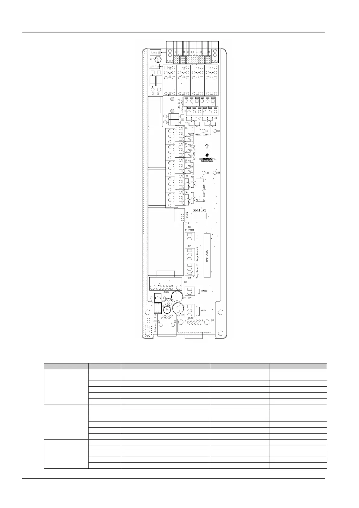
Figure 1.2 S6415X2 interface
Table 1.2 Interface functions
Connector Pin Signal name Mark number Logic relation
J3
1 Relay output 1 normal close DO1_NC
2 Relay output 2 normal close DO2_NC
3 Relay output 1 common DO1_COM
4 Relay output 2 common DO2_COM
5 Relay output 1 normal open DO1_NO
6 Relay output 2 normal open DO2_NO
J4
1 Relay output 3 normal close DO3_NC
2 Relay output 4 normal close DO4_NC
3 Relay output 3 common DO3_COM
4 Relay output 4 common DO4_COM
5 Relay output 3 normal open DO3_NO
6 Relay output 4 normal open DO4_NO
J5 1 Relay output 5 normal close DO5_NC
2 Relay output 6 normal close DO6_NC
3 Relay output 5 common DO5_COM
4 Relay output 6 common DO6_COM
5 Relay output 5 normal open DO5_NO
NetSure 501 A50, NetSure 501 AA0, NetSure 701 A51 19-Inch Subrack Power Supply System User Manual
 Loading...