Do you have a question about the Emerson NetSure 211 C45 and is the answer not in the manual?
Covers crucial safety guidelines related to electrical hazards and operations.
Details risks associated with direct/indirect contact with hazardous voltages.
Emphasizes the mandatory use of specialized tools for high voltage work.
Warns against operating during thunderstorms due to electromagnetic interference.
Explains ESD hazards and necessary precautions for component protection.
Outlines the dangers and prevention methods for short circuits in DC systems.
Describes the BLVD function for battery protection and its settings.
Safety advice for replacing fuses and general equipment handling.
Recommends wearing protective gloves to avoid injury from sharp objects.
Guidance on verifying power cable labels before connection.
Recommendations for routing signal cables away from power cables.
Details the model designation and its components.
Describes the system's composition and configurations for different models.
Lists key features and technologies of the power supply system.
Essential safety rules for system installation personnel.
Covers unpacking, inspection, and cable selection for installation.
Instructions for installing brackets and the power supply subrack.
Procedures for connecting power and signal cables to the system.
Steps for performing installation checks and system startup procedures.
Configuration of monitoring module parameters for system operation.
Verifying alarm triggers and system operational status.
Concluding actions after installation and testing, including reporting.
Classifies alarms and provides troubleshooting methods for common issues.
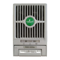
Details rectifier indicators and methods for handling rectifier faults.
Specifies operating conditions like temperature, humidity, and altitude.
Technical specifications for AC input voltage, frequency, and current.
Technical specifications for DC output voltage, current, and regulation.
Details alarm and protection points for AC input over/under-voltage.
Details alarm and protection points for DC output over/under-voltage and BLVD.
Technical data related to rectifier performance, protection, and derating.
Electromagnetic compatibility standards and immunity levels.
Physical dimensions and weight specifications for the system.
Illustrates the wiring connections for the C45-S1 power supply system.
Illustrates the wiring connections for the C45-S2 power supply system.
Glossary of abbreviations used in the manual with their full words.
| Brand | Emerson |
|---|---|
| Model | NetSure 211 C45 |
| Category | Power Supply |
| Language | English |