8 Chapter 2 Installation Instruction
NetSure 211 C45 Embedded Power Supply System User Manual
Refer to Table 2-8 to connect the input and output cables.
Table 2-8 Connection descriptions of input and output cables
Lead the AC input cables through the AC cable entry hole, and reinstall the back cover.
1. Cable connection of NetSure 211 C45-S2 power supply system
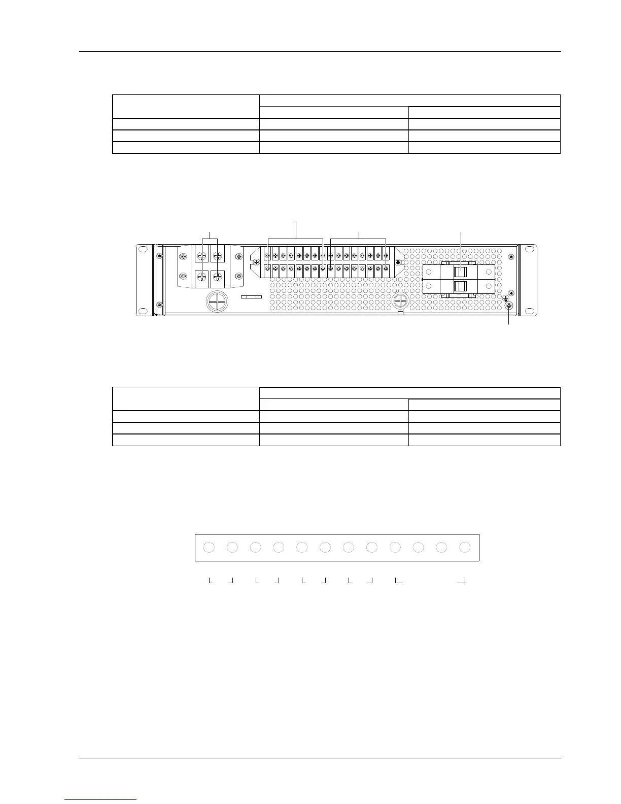
The positions of the connection terminals are shown in Figure 2-7.
Battery connection terminal
Load connection terminal
Dry contact AC input MCB
Earth terminal
Figure 2-7 Connection terminals (back view)
Refer to Table 2-9 to connect the input and output cables.
Table 2-9 Connection descriptions of input and output cables
Battery connection terminal
2.4.2 Connecting Signal Cables
1. Cable connection of NetSure 211 C45-S1 power supply system
The position of the dry contact and temperature probe connection terminal is shown in Figure 2-5, and the screen
print is shown in Figure 2-8.
+ - + -
NO COM NO COM PS Ground T1 T2
DO2DO1DI2DI1 Temp. sensor
Figure 2-8 Dry contact and temperature probe connection terminal
Connection method:
Peel one end of the signal cable and insert it into the dry contact and temperature probe connection terminal. Fasten
the connection by tightening the screw on the terminal.

 Loading...