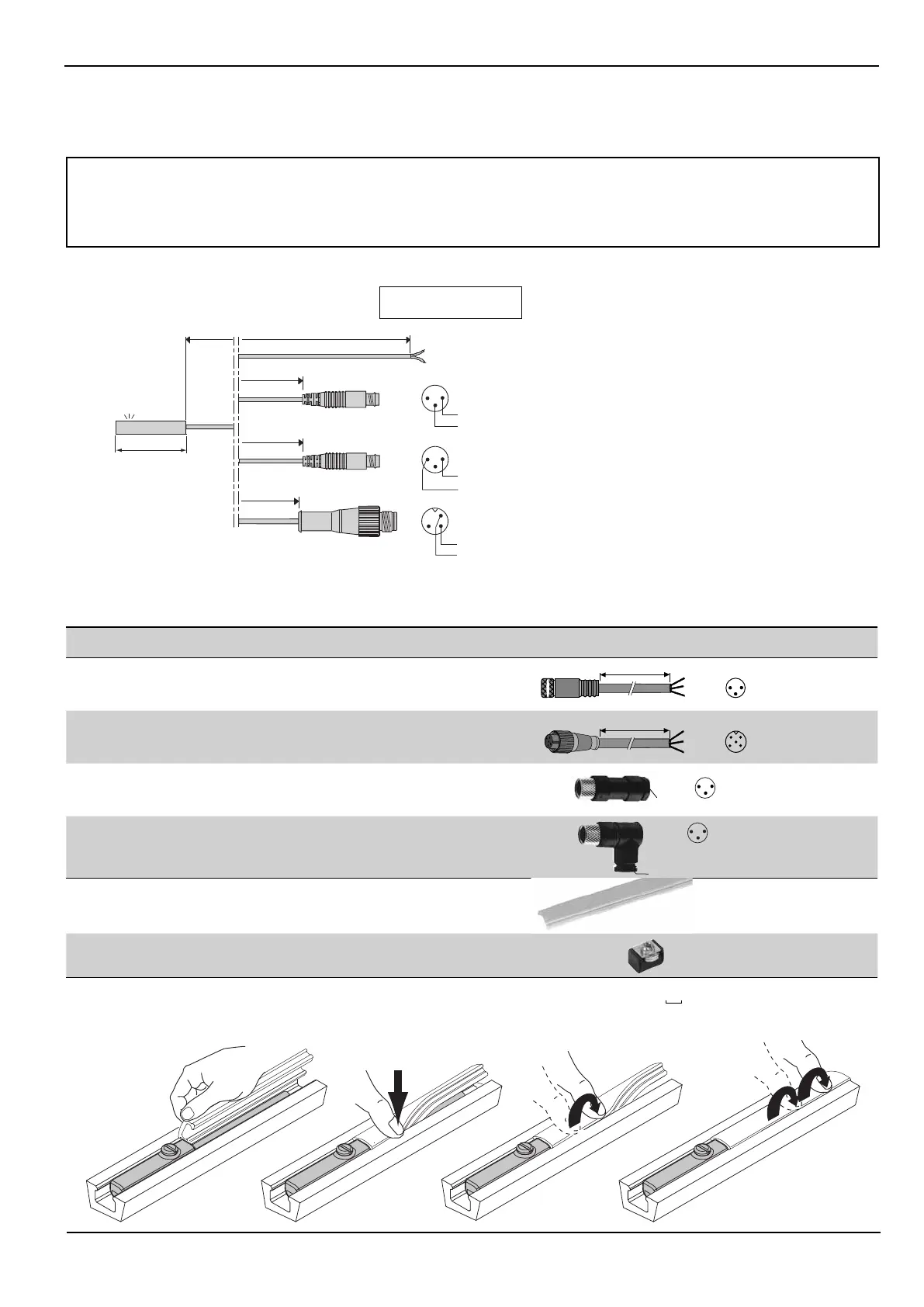
REED SWITCH CONNECTION : 4 possibilities
View from male contact
side of connector
PUR lead outlet Ø 3 mm with 3-pin plug-in male
connector + screw Ø 8 mm (2 pins connected, 1 and 4)
PUR lead outlet Ø 3 mm resistant to cutting fl uids, with
3-pin screw-type male connector, Ø M12 (2 pins connected, 1 and 4)
PUR lead outlet Ø 3 mm with 3-pin plug-in male
connector + screw Ø 8 mm (2 pins connected, 1 and 3)
PUR lead outlet Ø 3 mm with stripped ends,
2 wires 0.14 mm
2
- brown wire = +
blue wire = -
1
3
4
1
3
4
1
3
4
30 mm
0,3 m
0,3 m
0,3 m
2 / 5 m
(1) For your order please add the requested length (in metres) to the order code - example: 2 m = 88100746 2
ACCESSORIES
description
catalogue
number
extension consisting of PVC, length 5 m, 3 wire conductors 0.25 mm
2
with 1 screw-on femal M8 connector (other end plain)
, IP67
5 m
br
= 1
blk= 4
blu= 3
1
4
3
PVC
88100239
extension consisting of PVC, length 5 m, 3 wire conductors 0.25 mm
2
with 1 screw-on femal M12 connector (other end plain)
, IP67
5 m
br
= 1
blk= 4
blu= 3
1
4
3
2
PVC
88100238
straiht 3-pin female connector Ø M8, IP67
88100202
Right angle 3-pin female connector Ø M8, orientable 90° x 90°, IP67
1
3
4
CM5
88100203
Cable cover and holder
(sold by the metre - minimum length = 1 m)
«T» slot 88100746 (1)
Block of memorizing position of adjustment detector
N199-1162
Mounting recommendation:
Do not subject the detector's power supply cable to damaging traction / torsion during its service life.
ASSEMBLY OF CABLE COVER AND HOLDER
2
MAXIMUM ELECTRICAL CHARACTERISTICS AND PROTECTION OF MAGNETIC DETECTOR (REED SWITCH)
Max. switching current : 100mA
For inductive loads (valves, contactors, …), external protection is required to avoid damage caused by switch-off voltage peaks. Use
freewheeling diode, transil diode, varistor or similar.
PARTICULAR APPLICATIONS (valid for all models)
• Detectors used for direct control of incandescent lamps:
The capacity specifi ed on the lamp is based on its resistance when hot. When switched on, the resistance of the cold lamp is very low. Therefore,
the current rises quickly and may exceed the reed switch rating. Allowance should therefore be made for the real power of the cold lamp.
• With leads longer than 10 m, a 200 Ω resistor must be fi tted in series with the detector to reduce the capacitive effect caused by the wiring.
 Loading...