10
Reference Manual
00809-0200-4975, Rev A
HART Menu Structure
June 2017
HART Menu Structure
5.2 Root menu
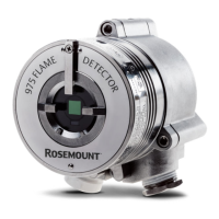
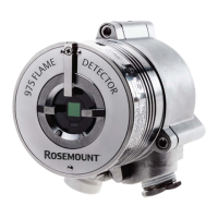
When HART communication is established with the Rosemount 975 Flame Detector, the Root menu
opens.
Figure 5-2. .Root Menu
Table 5-1. Root Menu Commands
1 Manufacturer Rosemount, Inc. Read
2 Model 975 Read
3 Dev ID Device unique identification number Read
4 Dev. Model
Device sensor type (see Annex B, Table B1: Fire Detection
Sensor Type Codes
Read
5 PV Snsr s/n Device serial number Read
6 Tag
User-definable text up to 16 characters in length
associated with the field device installation.
R/W
7 Long Tag
User-definable text up to 32 characters in length
associated with the field device installation.
R/W
8 Descriptor User-definable text associated with the field device. R/W
9 Message User-definable text associated with the field device. R/W
10 Final asmbly num
A number associated with the field device used for
identification purposes.
R/W
11 Date A user-definable date. R/W
12 Status
Indicates a field device condition. Refer to Appendix A:
Field Device Status.
Read
13 Self Test
Performs internal tests. Detected problems are displayed
in the Status menu.
Button
14 Status menu Displays current status and diagnostic information. Menu
15 Device Setup menu Setup and configuration functions Menu
16 HART Output menu HART-specific variables Menu
 Loading...