1-7-1 T7300EA
ELECTRICAL ADJUSTMENT INSTRUCTIONS
General Note:
"CBA" is abbreviation for "Circuit Board
Assembly."
NOTE:
Electrical adjustments are required after replacing
circuit components and certain mechanical parts.
It is important to perform these adjustments only
after all repairs and replacements have been com-
pleted.
Also, do not attempt these adjustments unless the
proper equipment is available.
Test Equipment Required
1. NTSC Pattern Generator (Color Bar W/White Win-
dow, Red Color, Dot Pattern, Gray Scale, Mono-
scope, Multi-Burst)
2. AC Milli Voltmeter (RMS)
3. Alignment Tape (FL8A, FL8N), Blank Tape
4. DC Voltmeter
5. Oscilloscope: Dual-trace with 10:1 probe,
V-Range: 0.001~50V/Div,
F-Range: DC~AC-60MHz
6. Frequency Counter
7. Plastic Tip Driver
How to make service remote control
unit:
1. Prepare normal remote control unit. (Part No.
N0107UD) Remove 3 screws from the back lid.
(Fig. 1-1)
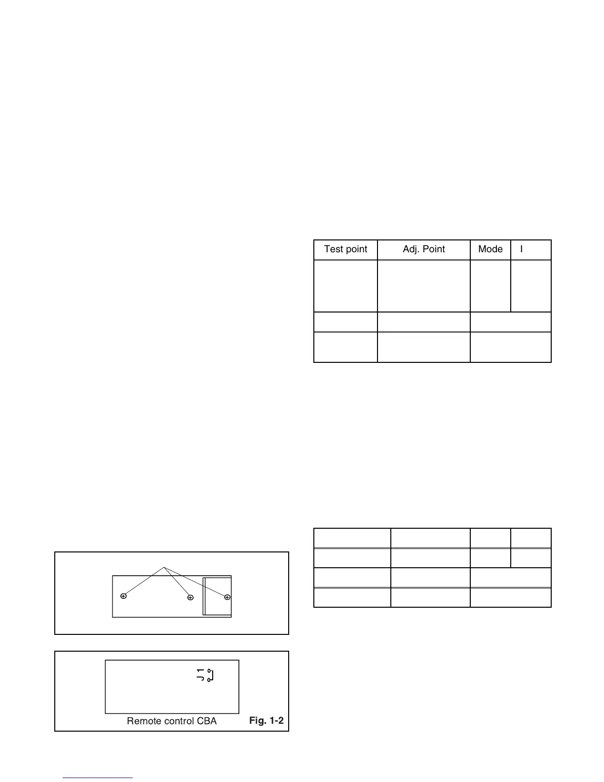
2. Added J1 (Jumper Wire) to the remote control
CBA. (Fig. 1-2)
How to Set up the Service mode:
Service Mode:
1. Use the service remote control unit.
2. Turn the power on.
3. Press " WAKE-UP/SLEEP " button on the service
remote control unit.
1. DC 114V (+B) Adjustment
Purpose: To obtain correct operation.
Symptom of Misadjustment: The picture is dark and
unit does not operate correctly.
Note: J192(+B), J213(GND), VR601 --- Main CBA
1. Connect the unit to AC Power Outlet.
2. Connect DC Volt Meter to J192(+B) and
J213(GND).
3. Adjust VR601 so that the voltage of J192(+B)
becomes +114±0.5V DC.
2. Auto AFT (VCO) Adjustment
Purpose: To operate AFT correctly.
Symptom of Misadjustment: AFT does not work cor-
rectly and/or synchronization is faulty.
1. Set the unit to the Video mode with no signal input.
2. Enter the Service mode. (See page 1-4-1.) Then
press number "3" button on the remote control unit.
3. If the screen color changes to "Green" then this
adjustment is finished.
4. If the screen color changes to "Red" then this
adjustment is failed. Repeat steps 1 and 2 or check
relative circuit or parts (IC).
SCREW
Fig. 1-1
Remote control unit (Bottom)
J1
Remote control CBA
Test point Adj. Point Mode Input
J192
(+B)
J213
(GND)
VR601 --- -----
Tape M. EQ. Spec.
---
DC Voltmeter
Plastic Tip Driver
+114±0.5V DC
Test point Adj. Point Mode Input
--- --- Video -----
Tape M. EQ. Spec.
--- --- ---