CPU Modules CPU001 and CPU002
October 2005 GFK-1536P
3
Module Installation
This equipment may be mounted on a horizontal or vertical DIN rail.
If mounted on a vertical DIN rail, the CPU module must be located at
the bottom. The CPU and connecting carriers must be installed on
the same section of 35mm x 7.5mm DIN rail, 1mm thick. Steel DIN
rail is recommended. The DIN rail must be electrically grounded to
provide EMC protection. The rail must have a conductive (unpainted)
corrosion-resistant finish. DIN rails compliant with DIN EN50022 are
preferred. For vibration resistance, the DIN rail should be installed
on a panel using screws spaced approximately 15.24cm (6 inches)
apart.
Rated thermal specifications for the CPU module are based on a
clearance of 2” above and below the equipment and 1” to the left of
the CPU module.
1. Allow sufficient finger clearance for opening CPU door.
2. Allow adequate clearance for serial port and Ethernet cables.
3. Allow adequate space for power wiring.
The CPU with power supply attached fits into a 70mm deep
enclosure.
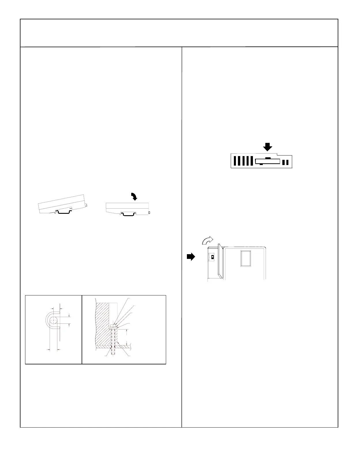
Installing the CPU on the DIN Rail
The CPU snaps easily onto the DIN rail. No tools are required for
mounting or grounding to the DIN rail.
Before joining module carriers to the CPU, remove the connector
cover on the right-hand side of the CPU. Do not discard this cover,
you will need to install it on the last carrier, to protect the connector
pins from contamination and damage during use.
Panel-Mounting
If excessive vibration is a factor the CPU should also be screwed
down to the mounting panel.
Note 1. Tolerances are +/- 0.13mm (0.005in) non-cumulative.
Note 2. 1.1-1.4Nm (10-12 in/lbs) of torque should be applied to M3.5
(#6-32) steel screw threaded into material containing internal
threads and having a minimum thickness of 2.4mm
(0.093in).
SEE NOTE 2.
M3.5 (#6) SCREW
15.9mm
0.62in REF
SPLIT LOCK
WASHER
FLAT WASHER
CPU
TAPPED
HOLE IN
PANEL
5.1mm
0.200in
4.3mm
0.170in
4.3mm
0.170in
Removing the CPU from the DIN Rail
1. Turn off power to the power supply.
2. (If the CPU is attached to the panel with a screw) remove the power
supply module. Remove the panel-mount screw.
3. Slide the CPU away from the other modules until the connector on
the right side disengages from the next carrier.
4. With a small flathead screwdriver, pull the DIN rail latch outward
while tilting the other end of the module down to disengage it from
the DIN rail.
Activating or Replacing the Backup Battery
The CPU is shipped with a battery already installed. The battery holder
is located in the top side of the CPU module. Before the first use,
activate the battery by pulling and removing the insulator tab.
To replace the battery, use a small screwdriver to gently pry open the
battery holder. Replace battery only with*ACC001 from your PLC
supplier, or with Panasonic battery: BR2032. Use of another battery may
present a risk of fire or explosion.
Caution
Battery may explode if mistreated.
Do not recharge, disassemble, heat above 100 deg.C (212 deg.F) or
incinerate.
Switching the PLC Operating Mode
RUN/ON
STOP/OFF
The CPU Run/Stop mode
switch is located behind the
module door. This switch can
be used to place the CPU in
Stop or Run mode. By default.
Run/Stop mode operation is
enabled. The same switch can
also be configured to prevent
writing to program or
configuration memory and
forcing or overriding discrete
data. It defaults to disabled
memory protection.
If Run/Stop mode switch operation is enabled, the switch can be used to
place the CPU in Run mode.
If the CPU has non-fatal faults and is not in Stop/Fault mode, placing the
switch in Run position causes the CPU to go to Run mode. Faults are
NOT cleared.
If the CPU has fatal faults and is in Stop/Fault mode, placing the switch
in Run position causes the Run LED to blink for 5 seconds. While the
Run LED is blinking, the CPU switch can be used to clear the fault table
and put the CPU in Run mode. After the switch has been in Run position
for at least ½ second, move it to Stop position for at least ½ second.
Then move it back to Run position. The faults are cleared and the CPU
goes to Run mode. The LED stops blinking and stays on. This can be
repeated if necessary.
If the switch is not toggled, after 5 seconds the Run LED goes off and
the CPU remains in Stop/Fault mode. Faults stay in the fault table.