CPU Modules CPU001 and CPU002
October 2005 GFK-1536P
4
Observing the Module LEDs
PORT 2
FORCE
PORT 1
FAULT
RUN
PWR
OK
The LEDs indicate the presence of power and show the
operating mode and status of the CPU.
POWER
ON when the CPU is receiving 5V power from the power supply.
Does not indicate the status of the 3.3V power output.
OK
ON indicates the CPU has passed its powerup diagnostics and is
functioning properly. OFF indicates a CPU problem. Fast blinking
indicates the CPU is running its powerup diagnostics. Slow blinking
indicates the CPU is configuring I/O modules. Simultaneous blinking
of this LED and the green Run LED indicates the CPU is in boot
mode and is waiting for a firmware download through port 1.
RUN
Green when the CPU is in Run mode. Amber indicates the CPU is
in Stop/IO Scan mode. If this LED is OFF but OK is ON, the CPU is
in Stop/No IO Scan mode.
If RUN is flashing green and the Fault LED is ON, the Run/Stop
switch was moved to Run position while a fatal fault existed.
FAULT
ON if the CPU is in Stop/Faulted mode because a fatal fault has
occurred. To turn off the Fault LED, clear both the I/O Fault Table
and the PLC Fault Table. If this LED is blinking and the OK LED is
OFF, a fatal fault has occurred during self-diagnostics. Please
contact PLC Product Support.
FORCE
ON if an override is active on a bit reference.
PORT 1 & 2
Blinking indicates activity on that port.
Using the CPU Serial Ports
The CPU’s two serial ports are software-configurable for SNP slave,
RTU slave, or Serial I/O operation. If a port is being used for RTU, it
automatically switches to SNP slave mode if necessary. Both ports’
default configuration is SNP slave mode. If configured for Serial I/O,
a port automatically reverts to SNP slave when the CPU is in Stop
mode.
Either port can be software-configured to set up communications
between the CPU and various serial devices. An external device can
obtain power from Port 2 if it requires 100mA or less at 5VDC.
RS485
PORT 2
1
8
RS232
PORT 1
1
5
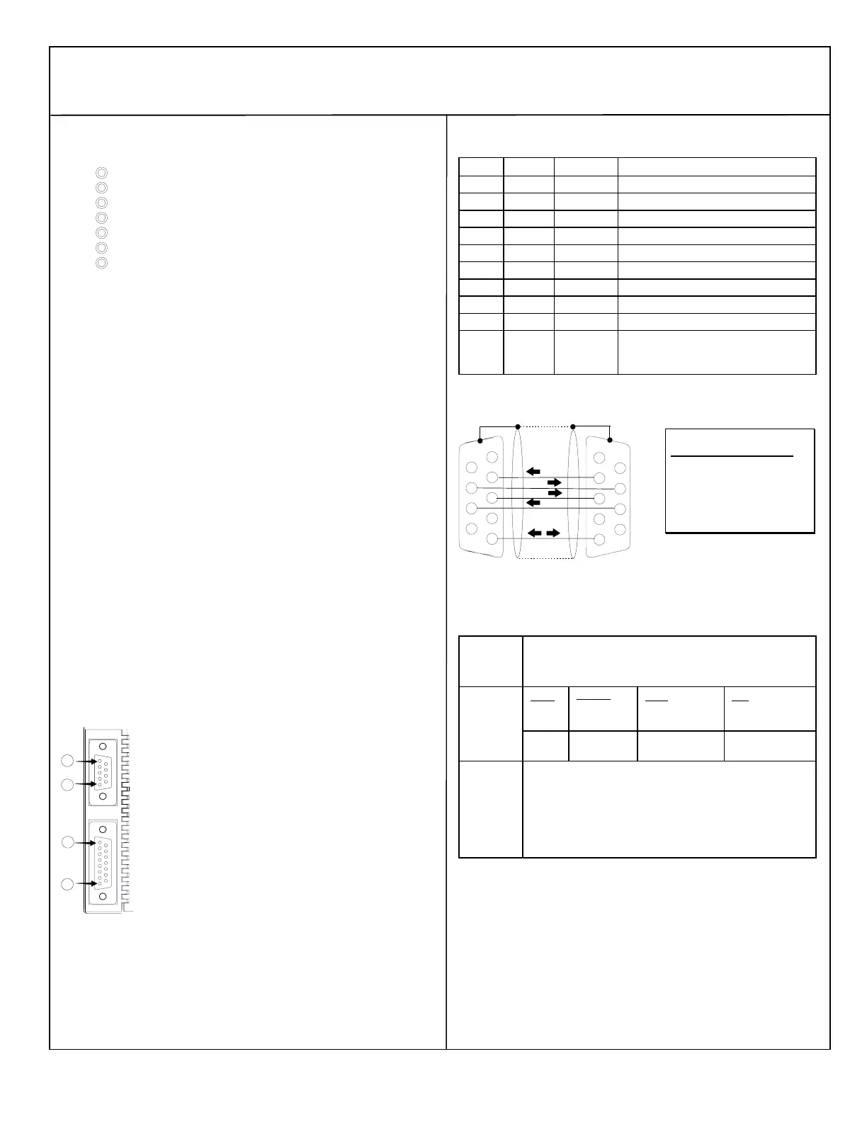
Port 1 is an RS-232 port with a 9-pin female D-sub connector. It
is used as the boot loader port for upgrading the CPU firmware.
The pinout of port 1 allows a simple, straight-through cable to
connect with a standard AT-style RS-232 port. Cable shielding
attaches to the shell. Port 1 screw locks are threaded #4-40.
Port 2 is an RS-485 port with a 15-pin female D-sub connector.
This can be attached directly to an RS-485 to RS-232 adapter
(IC690ACC901). Port 2 can be use for program, configuration,
and table updates with the EZ Program Store module. Port 2
screw locks are threaded (metric) M3x0.5).
Pin Assignments for Port 1
Pin Signal Direction Function
1 n/c --
2 TXD Output Transmit Data output
3 RXD Input Receive Data input
4 n/c --
5 GND -- 0V/GND signal reference
6 n/c --
7 CTS Input Clear to Send input
8 RTS Output Request to Send output
9 n/c --
Shell SHLD -- Cable Shield wire connection / 100%
(Continuous) shielding cable shield
connection
Cable Diagram for Attachment to a PC
2
6
7
8
9
3
4
5
2
6
7
8
9
3
4
5
1
1
The shield must attach to shell of
connectors on both ends of the cable.
PC 9-Pin CPU
Serial Port Port 1
9-pin female 9-pin male
(2) RXD (2) TXD
(3) TXD (3) RXD
(5) GND (5) GND
(7) RTS (7) CTS
(8) CTS (8) RTS
Connector and Cable Specifications for Port 1
Vendor Part numbers below are provided for reference only. Any part
that meets the same specification can be used.
Cable:
Belden
9610
Computer cable, overall braid over foil shield
5 conductor †
30 Volt / 80°C (176°F)
24 AWG tinned copper, 7x32 stranding
9 Pin Male
Connector:
Type:
Crimp
Vendor:
ITT/Cannon
AMP
Plug:
DEA9PK87F0
205204-1
Pin:
030-2487-017
66506-9
Solder ITT/Cannon
AMP
ZDE9P
747904-2
--
--
Connector
Shell:
Kit* – ITT Cannon DE121073-54 [9-pin size backshell kit]:
Metal-Plated Plastic (Plastic with Nickel over Copper) †
Cable Grounding Clamp (included)
40° cable exit design to maintain low-profile installation
Plus – ITT Cannon 250-8501-010 [Extended Jackscrew]:
Threaded with #4-40 for secure attachment to port †
Order Qty 2 for each cable shell ordered
† Critical Information – any other part selected should meet or exceed this criteria.
* Use of this kit maintains the 70mm installed depth.