4
GB | Wireless Weather Station
Read this manual carefully before using the product.
Specications
radio-controlled clock
time format: 12/24 h
indoor temperature: -10 °C to +50 °C, 0.1 °C resolution
outdoor temperature: -40 °C to +60 °C, 0.1 °C resolution
accuracy of temperature measurement: ±1 °C for 0 °C to +50 °C range, ±1.5 °C for other ranges
indoor and outdoor humidity: 1 % to 99 % RH, 1 % resolution
accuracy of humidity measurement: ±5 % for 30 % to 80 % RH range, ±8 % for 20 % to 29 % and
for 81 % to 95 % RH, ±12 % for 1 % to 19 % range and 96 % to 99 % range
temperature and humidity measurement cycle: every 30 seconds
measured value outside the listed range: displays LL.L/HH.H
barometric pressure measurement range: 800 hPa to 1,100 hPa
unit of pressure: mmHg, inHg, hPa/mb
radio signal range: up to 80 m in an open area
transmission frequency: 433 MHz, 10 mW e.r.p. max.
number of sensors: max. 3
power supply:
main station: 3× 1.5 V AA batteries (not included)
adapter: 230 V AC/5 V DC, 1,200 mA (included)
sensor: 2× 1.5 V AA batteries (not included)
size:
main station: 30 × 200 × 130 mm
sensor: 20 × 38 × 100 mm
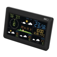
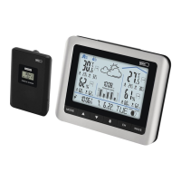
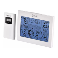
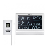
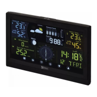
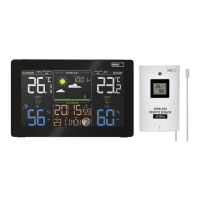
Weather Station – Screen (See Fig. 1)
1 – data from outdoor sensor
2 – channel number of the outdoor sensor,
rotation of data from connected sensors
3 – weather forecast
4 – glaze ice warning
5 – data from the station‘s indoor sensor
6 – indoor temperature, temperature trend
arrow
7 – station batteries low
8 – indoor humidity, humidity trend arrow
9 – comfort level indicator – smiley
10 – automatic dimming of screen illumination
11 – moon phase
12 – day of the week
13 – calendar day
14 – alarm
15 – snooze
16 – month
17 – time
18 – DCF signal reception
19 – pressure value
20 – outdoor humidity, humidity trend arrow
21 – sensor batteries low
22 – temperature limit
23 – outdoor temperature
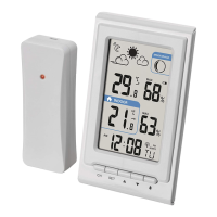
Description of Buttons (See Fig. 2)
1 – SNOOZE/LIGHT
2 – connector for plugging in the power
adapter
3 –
alarm settings
4 – ALERT
5 – MEM
6 –
7 –
8 – SET
9 – hole for hanging on a wall
10 – battery compartment
11 – stand
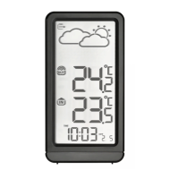
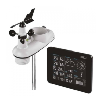
Sensor Description (See Fig. 3)
1 – LED
2 – hole for hanging on a wall
3 – channel switch (CH 1, 2, 3)
4 – battery cover