3
• Do not measure voltages and currents higher than
indicated on the front panel of the multimeter.
Risk of injury by electric current or damage to
the multimeter!
• Check that the multimeter is working properly
before use. Test on a circuit with known electrical
values.
• Before you connect the multimeter to a circuit you
intend to measure, turn o the power to the circuit.
• If you need to replace a component of the mul-
timeter (e.g. battery, fuse), always use spare parts
of the same type and specifications. Change
parts only when the multimeter is disconnected
and turned o.
• Do not alter or otherwise interfere with the internal
circuitry of the multimeter!
• Be extra careful when measuring voltages higher
than 30 V AC rms, 42 V peak or 60 V DC. Risk of
injury by electric current!
• When using measuring tips, make sure you are
holding them behind the nger barriers.
• Disconnect the measuring tips from the tested cir-
cuit before opening the casing of the multimeter.
• Do not perform measurements if the multimeter‘s
casing is removed or loose.
• Change the battery once the low battery warning
indicator
appears on the screen. Otherwise,
subsequent measurements may be inaccurate.
Incorrect measurements may then result in injuries
by electric current!
ATTENTION
Use multimeter MD-210 only in the manner specied
below. Otherwise, the device could get damaged or
the user may suer injury. Comply with the following
instructions:
Before measuring resistance, diodes or current, discon-
nect the circuits from the power supply and discharge
the high-voltage capacitors.
Before measuring, make sure the circular switch for
measuring range is in the correct position. Under no
circumstances should you make any changes to the
measuring range (by moving the circular switch for
measuring programs) while measuring. Doing so could
damage the device.
If you intend to measure current, check the multimeter‘s
fuse and turn o the power supply to the circuit before
you connect the multimeter.
When you are measuring, rst connect the black con-
ductor (probe) and then the red conductor (probe).
When disconnecting the testing conductors, discon-
nect the red one rst.
Maintenance Instructions
Attention
Do not attempt to repair or modify the multimeter in
any way if you are not qualied for the task or do not
have access to the necessary calibration equipment.
To prevent injury by electric current, make sure that
water does not enter the inside of the multimeter!
• Disconnect the measuring tips from the tested cir-
cuit before opening the casing of the multimeter.
• Regularly clean the body of the multimeter with a
moist cloth and a mild detergent. Perform cleaning
only when the multimeter is disconnected and
turned o.
• Do not use solvents or abrasive agents for cleaning!
• If you are not using the multimeter for an extended
period of time, turn it o and remove the batteries.
• Do not store the multimeter in places with high
humidity and temperature or in places with a
strong magnetic eld!
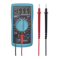
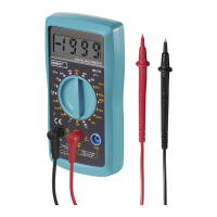
Device Description
Multimeter MD-210 is a compact device with a 3.5
digit display. It is designed for measuring direct and
alternating voltage, direct and alternating current,
resistance, temperature, test diodes and perform audio
testing of conductivity and of circuits. The multimeter
provides protection against overload and informs the
user when the battery is low. It is ideal for use in e.g.
workshops, laboratories and households.
Front View of the Multimeter
1 – Screen – displays 3.5 digits i.e. a maximum value
of 1999
2 – Function and range switch – allows selecting
functions and the desired range as well as turning
the multimeter on or o. If you are not using the
multimeter, turn it o. The battery will then last
you longer.
3 – 10 A socket – used for connecting the plug of the red
(positive) tipped measuring conductor to measure
currents in 10 A DC current range.
4 –
socket – used for connecting the plug of the red
(positive) tipped measuring conductor to measure
voltage, resistance or current to up to 200 mA.
5 – COM socket – used for connecting the plug of the
red (positive) tipped measuring conductor.
Specications
Screen: LCD, 1999 (3.5 digits) with automatic polarity
indication
Measuring method: dual-slope integration via an
A/D converter
Reading frequency: 2–3× per second
Operating temperature and humidity: 0°C to 40°C,
<75 %
Storage temperature and humidity: -10°C to 50°C,
relative humidity <85 %
Power supply: 1× 9 V (6F22) battery
Fuses: F 250 mA/300 V, ø 5×20 mm, F 10 A/300 V,
ø 5×20 mm
Low battery: indication via a battery symbol on the
screen
Indication of exceeded range: shows „OL“ on the LCD
Measuring category: CAT III (300 V)
Enclosure: IP20
Dimensions 28 × 138 × 70 mm
Weight: 141 g (battery included)