4
Accuracy
The stated accuracy is for a period of one year since
calibration of the device at 18°C to 28°C and relative
humidity of up to 75 %.
Measurement accuracy is stated as: ± [(% of reading) +
(lowest valid digits)].
DC Voltage
Range Resolution Accuracy
200 mV 100 µV +(0.5 % + 5)
2 V 1 mV
+(0.8 % + 5)20 V 10 mV
200 V 100 mV
300 V 1 V +(1 % + 5)
Input impedance: 1 MΩ
Maximum input voltage: 300 V DC
AC Voltage
Range Resolution Accuracy
200 V 100 mV
+(1.2 % + 10)
300 V 1 V
Frequency range: 40 Hz to 400 Hz
Maximum input voltage: 300 V AC
Note: The value is an average corresponding to the cali-
brated eective sine wave.
Direct current (DC)
Range Resolution Accuracy
20 µA 0.01 µA +(1.2 % + 5)
200 µA 0.1 µA
+(1 % + 5)2 000 µA 1 µA
20 mA 10 µA
200 mA 100 µA +(1.2 % + 5)
10 A 10 mA +(2 % + 5)
Overload protection:
μA and mA range: F 250 mA/300 V fuse
10 A range: F 10 A/300 V fuse
Maximum input current:
socket: max. 200 mA
10 A socket: max. 10 A
When measuring currents larger than 2 A: measure-
ment duration must be max. 10 seconds and meas-
urement may only be repeated again after 15 minutes!
Resistance
Range Resolution Accuracy
200 Ω 0.1 Ω
+ (1.2 % + 5)
2 kΩ 1 Ω
20 kΩ 10 Ω
200 kΩ 100 Ω
2 MΩ 1 kΩ
Voltage of an open circuit: max. 1 V
Diode and Circuit Continuity Test
Range Description Note
The approximate
voltage of the diode
in the direction of the
current ow will appear
on the screen
Voltage
without load:
2.2 V
Built-in buzzer indicates
that resistance in the
circuit is lower than
20 Ω; If resistance is
between 20 Ω and
150 Ω the buzzer may
or may not sound.; If
resistance is higher
than 150 Ω; the buzzer
will not sound
Voltage
without load:
2.2 V
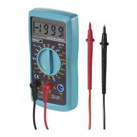
Measuring Direct Voltage
1. Connect the plug of the red measuring conductor
into the
socket and the black conductor into
the COM socket.
2. Turn the circular switch to function marked
.
Choose a measuring range and place the meas-
uring tips the spot or circuit where you wish to
measure DC voltage.
If you do not know the voltage range beforehand,
set the highest possible range and gradually decrease
it as you measure.
3. Turn on the device you want to measure. The
screen will display the voltage value and polarity
relative to the red measuring tip.
If you exceed the range of 300 V, immediately stop
measuring. Otherwise, you risk damaging the multim-
eter and suering injury by electric current.
Measuring Alternating Voltage
1. Connect the plug of the red measuring conductor
into the
socket and the black conductor into
the COM socket.
2. Turn the circular switch to function marked .
Choose a measuring range and place the meas-
uring tips the spot or circuit where you wish to
measure AC voltage.
If you do not know the voltage range beforehand,
set the largest possible range and gradually decrease
it as you measure.
3. Turn on the device you want to measure. The
screen will display the voltage value and polarity
relative to the red measuring tip.
If you exceed the range of 300 V, immediately stop
measuring. Otherwise, you risk damaging the multim-
eter and suering injury by electric current.