7
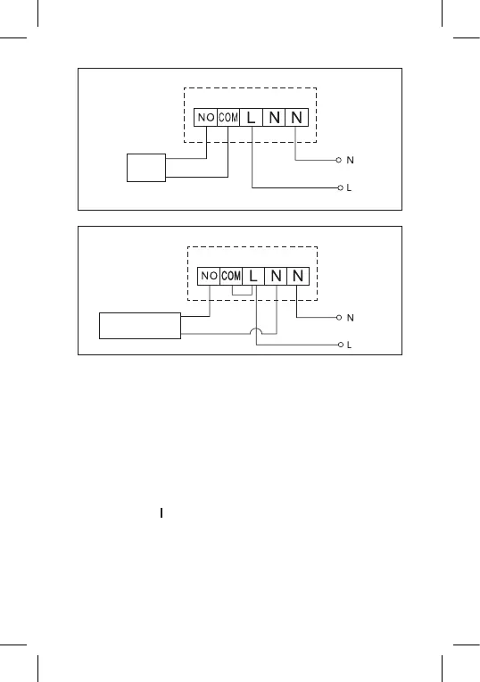
Boiler Connection Diagram
Boiler
Pre-installed wire coupler will not be connected.
Expansion Valve/Electric Drive Connection Diagram
Connected
device
PUTTING THE DEVICE INTO OPERATION
Pairing the Control Unit with the Switching Unit
Both thermostat units must be paired before rst use.
Pairing enables transfer of information between the control unit and
the switching unit.
Setting is done via automated pairing (self-learning).
1. Remove the cover of the thermostat (transmitter) and insert 2×
1.5 V AAA batteries into the control unit (make sure polarity of
the batteries is correct). Only use alkaline batteries. Do not use
rechargeable batteries.
2. Correctly connect the switching unit to voltage supply, turn the main
switch to the position and long press (for at least 10 seconds) the
M/A button; a green diode will begin ashing.
3. Long press (for at least 3 seconds) the LEARN button on the ther-
mostat’s (transmitter’s) instrument panel.
The green diode on the switching unit will stop ashing and both units
are now paired.