EasyManuals Logo

EmpirBus NXT MCU User Manual

EmpirBus NXT MCU
8 pages
To Next Page IconTo Next Page
To Previous Page IconTo Previous Page
Page #3 background imageLoading...
Page #3 background image
EmpirBus NXT MCU User manual Ver 1.4 2/7
4.2,Connectors,
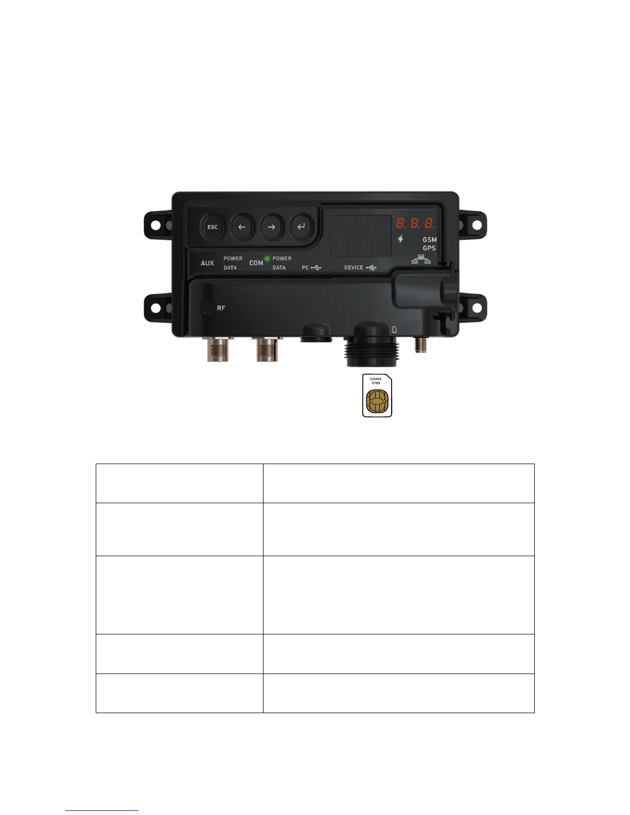
The bus connector is an NMEA 2000 compatible male Micro-C 5 pin connector. It is not
recommended to connect a T-connector directly on to the unit, a drop cable should be between the
main bus and the unit. The USB B mini connector is only designed to fit with an original MCU cable.
The MCU-200 and MCU-250 are equipped with a female SMA connector for GSM antenna
connection and a SIM card receptor that accepts mini-SIM. The SIM card is mounted behind the
yellow cap. See figure 4.2.
5. Product,specifica tions,
See table 3.1 for model specification and hardware support
Communication
CAN-bus
GSM
NMEA 2000
Quad-band 850/900/1700/1800MHz
Power supply
Max/average
Power consumption (power save)
Supply voltage
300mA/0,25mA
1.5mA
9-32VDC (Note: Power feed is through the NMEA 2000 bus)
Connectors
NMEA 2000
Antenna
SIM card
USB slave interface
CAN/RS232
Micro 5pin M12 Male
SMA female (MCU-200 & MCU-250)
mini-SIM (15 x 25 mm)
USB B mini
Micro 12 pin M12 Male (MCU-250)
Environment
Ambient temperature
Enclosure)
-20 to +70 degrees Celsius
Ingress Protection IP65, Polycarbonate
1
Physical data
Size
Weight)
173 x 89 x 32.5 mm
0.2 kg)
1)
Exposure)to)solvents )and/or)wa ter)above)60 °C) may)cause)cracking)on)polycarbonate.
Figure 4.2: MCU

Questions and Answers:

Question and Answer IconNeed help?

Do you have a question about the EmpirBus NXT MCU and is the answer not in the manual?

EmpirBus NXT MCU Specifications

General IconGeneral
BrandEmpirBus
ModelNXT MCU
CategoryControl Unit
LanguageEnglish