Do you have a question about the ENCLO Liberty Lattice ZP19054 and is the answer not in the manual?
| Brand | ENCLO |
|---|---|
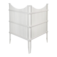
| Model | Liberty Lattice ZP19054 |
| Category | Lawn and Garden Equipment |
| Language | English |
Key details, contact info, and website for assistance with the winter cover kit.
Essential tips and warnings for safe and effective assembly of the cover kit.
Detailed physical measurements and technical specifications for the Liberty Lattice cover.
A guide to identifying and organizing all parts and fasteners for assembly.
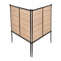
Initial setup of side frames for connecting the lattice boards.
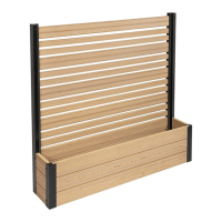
Sliding the front boards into the designated slots on the side frames.
Connecting middle boards by sliding into grooves and side frame slots.
Securing the back boards into the assembly structure.
Fastening the side frames using 1-inch self-drilling screws.
Positioning the front frame and fastening it with 2.5-inch screws.
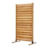
Sliding the assembled boards into the second side frame.
Fastening the second side frame using 1-inch screws.
Final step of placing the completed cover onto the AC unit.