SN: XXXXXXXXX
EDP141-230VAC-RS
DIGITAL POTENTIOMETER
ENDA INDUSTRIAL ELECTRONICS
1 2 3 4 5 6
7 8 9
10
11 12
GND
UP
-
+
A
B
230V AC +10% -20%
50/60Hz 7VA
0-10V DC OUTPUT
DOWN
RS-485 COM.
RS- 485
120 Ohm
120 Ohm
SN: XXXXXXXXX
EDP141-230VAC-RS
DIGITAL POTENTIOMETER
ENDA INDUSTRIAL ELECTRONICS
1 2 3 4 5 6
7 8 9
10
11 12
GND
UP
-
+
A
B
230V AC +10% -20%
50/60Hz 7VA
0-10V DC OUTPUT
DOWN
RS-485 COM.
RS- 485
SN: XXXXXXXXX
EDP141-230VAC-RS
DIGITAL POTENTIOMETER
ENDA INDUSTRIAL ELECTRONICS
1 2 3 4 5 6
7 8 9
10
11 12
GND
UP
-
+
A
B
230V AC +10% -20%
50/60Hz 7VA
0-10V DC OUTPUT
DOWN
RS-485 COM.
RS- 485
SN: XXXXXXXXX
EDP141-230VAC-RS
DIGITAL POTENTIOMETER
ENDA INDUSTRIAL ELECTRONICS
1 2 3 4 5 6
7 8 9
10
11 12
GND
UP
-
+
A
B
230V AC +10% -20%
50/60Hz 7VA
0-10V DC OUTPUT
DOWN
RS-485 COM.
RS- 485
SETSET
EDP141
ENDA
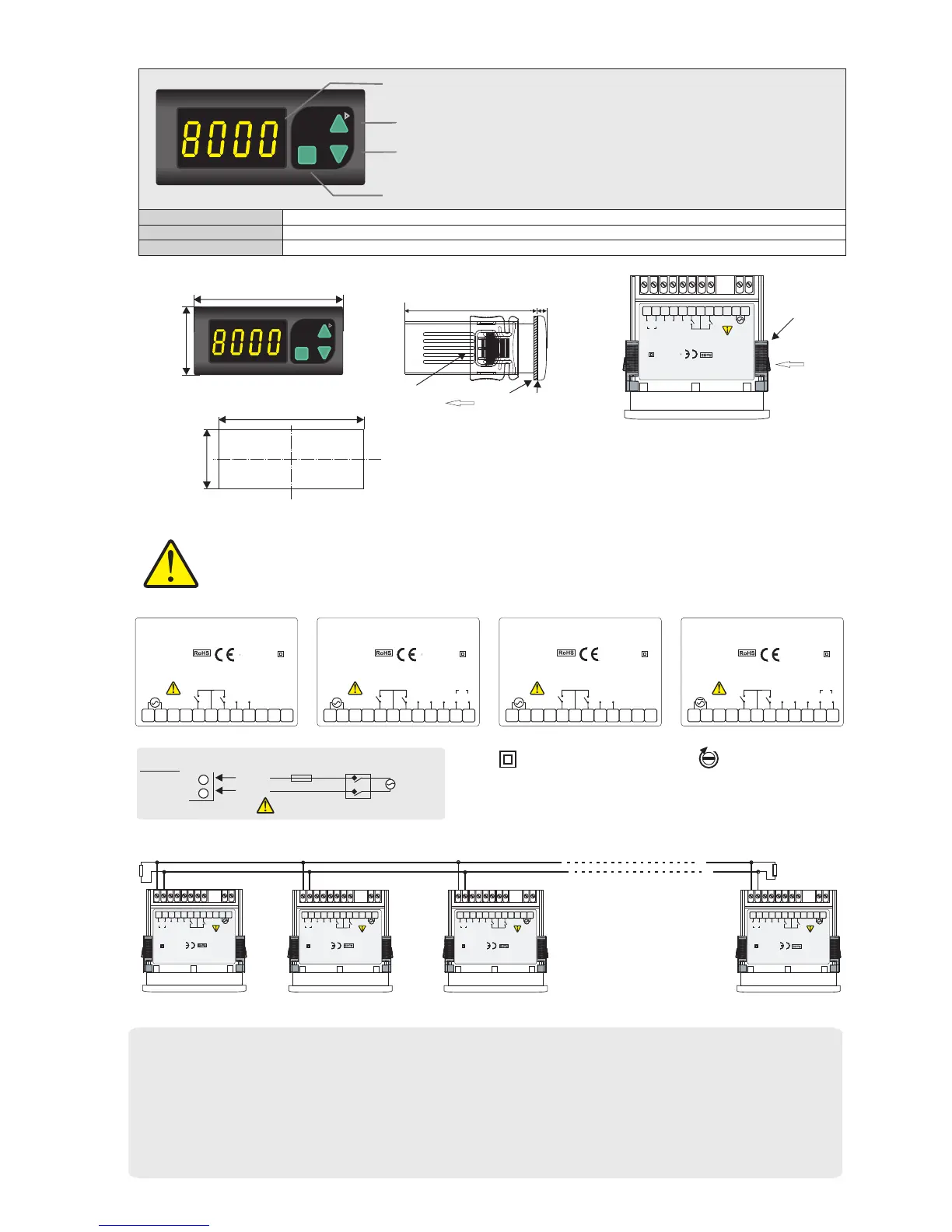
DIGITAL POTENTIOMETER
4 digits 7 segment yellow LED display
( 2 ),( 3 ),( 4 ) Keypad
( 1 ) Digital display
2/3
EDP141-E-08-R
12.5mm
Micro switch
1) Adjusted potentiometer value is seen in run mode
Parameter name, value or its unit in programming mode.
3) Decrement key during run mode.
Decrement or parameter selection key during programming mode.
2) Increment key during run mode.
Increment or parameter selection key during programming mode.
4) Used for selecting run or programming modes and for adjusting parameters.
TERMS
ENDA EDP 141 is intended for installation in control panels. Make sure that the device is used only for intended purpose.
must be grounded on the instrument side. During an installation, all of the cables that are connected to the device must be free of energy.
The device must be protected against inadmissible humidity, vibrations, severe soiling and make sure that the operation temperature is not
exceeded. All input and output lines that are not connected to the supply network must be laid out as shielded and twisted cables. These
cables should not be close to the power cables or components. The installation and electrical connections must be carried on by a
qualified staff and must be according to the relevant locally applicable regulations.
The shielding
CONNECTION DIAGRAM
Holding screw
0.4-0.5Nm
Equipment is protected throughout
by DOUBLE INSULATION.
Character height
Note : 1) Mains supply cords shall meet the requirements of IEC 60227 or IEC 60245.
2) In accordance with the safety regulations, the power supply switch shall bring the
identification of the relevant instrument and it should be easily accessible by the
operator.
Flush mounting
clamp
Note :
) Panel thickness should be maximum 7mm
2) If there is no 60mm free space at back side
of the device, it would be difficult to remove it
from the panel.
1
DIMENSIONS
1
Master
potentiometer
Slave
potentiometer-1
Slave
potentiometer-2
Slave
potentiometer-127
Max. 127 potentiometers
can be controlled.
NOTE :
- d.Adr. parameter should be selected C.Pot in master potentiometer. In this case d.Adr. parameter of other potentiometers aren’t used. But be sure that
C.Pot isn’t selected in slave potentiometers to prevent confusion. Settings of slave potentiometers change proportional to setting of master potentiometer.
For example; When Max. output of master potentiometer is changed from 10V to 5V, max. output of slave potentiometers decrease half of previous value
proportional to this. If previous output of slave potentiometer is 6V, it decreases 3V. P.on.c parameter of slave potentiometer should be selected oFF in
order to understand master potentiometer when slave is energized.
- Computer should be used to change only a few potentiometers. In this case, there is not master potentiomer. Output of the required potentiometer is
changed according to d.Adr. parameter.
- Baud rate of potentiometers must be same in both conditions. 120 Ohm termination resistor should be used at the ends and beginning of transmission
CONNECTION DIAGRAM FOR SYNCHRONOUS RUNNING
2
1
184-253V AC
50/60Hz 7VA
230V AC
Besleme
Anahtar
Fuse
F 100 mA 250V AC
Neutral
Line
SUPPLY :
NOTE :
Fuse should
be connected
Cable size: 1,5mm²
SN: XXXXXXXXX
EDP141-230VAC
DIGITAL POTENTIOMETER
ENDA INDUSTRIAL ELECTRONICS
1 2 3 4 5 6
7 8 9
10
11 12
GND
UP
230V AC +10% -20%
50/60Hz 7VA
0-10V DC OUTPUT
DOWN
SN: XXXXXXXXX
EDP141-24VAC
DIGITAL POTENTIOMETER
ENDA INDUSTRIAL ELECTRONICS
1 2 3 4 5 6
7 8 9
10
11 12
GND
UP
24V AC ±10%
50/60Hz 7VA
0-10V DC OUTPUT
DOWN
SN: XXXXXXXXX
EDP141-230VAC-RS
DIGITAL POTENTIOMETER
ENDA INDUSTRIAL ELECTRONICS
1 2 3 4 5 6
7 8 9
10
11 12
GND
UP
-
+
A
B
230V AC +10% -20%
50/60Hz 7VA
0-10V DC OUTPUT
DOWN
RS-485 COM.
RS- 485
SN: XXXXXXXXX
EDP141-SM-RS
DIGITAL POTENTIOMETER
ENDA INDUSTRIAL ELECTRONICS
1 2 3 4 5 6
7 8 9
10
11 12
GND
UP
-
+
A
B
0-10V DC OUTPUT
DOWN
RS-485 COM.
RS- 485
9-30V DC / 7-24V AC
±10 % 7VA
- Push up the flush-mounting
clamp in direction 1 as
shown in the figure above.
- Then, pull out the clamp in
direction 2.
For removing mounting clamps:
Flush mounting
clamp
SETSET
EDP141
ENDA
DIGITAL POTENTIOMETER
Panel cut-out
DIMENSIONS
71mm
29mm
Panel
Depth
2
71mm
5mm
35mm
77mm
Rubber
packing
SN: XXXXXXXXX
EDP141-230VAC-RS
DIGITAL POTENTIOMETER
ENDA INDUSTRIAL ELECTRONICS
1 2 3 4 5 6
7 8 9
10
11 12
GND
UP
-
+
A
B
230V AC +10% -20%
50/60Hz 7VA
0-10V DC OUTPUT
DOWN
RS-485 COM.
RS- 485
 Loading...
