1 / 4.
EDT2411A-EN-10052019
COM
B
A
END
A
INDUSTRIAL
ELECTRONICS
EDT241
1A-230-P-RS
DIGITAL THERMOST
AT
COMPRESSOR
277V 20A~
Made in TURKEY
1 2 3 4 5 6
7 8 9
10
ENDA INDUSTRIAL ELECTRONICS
SN: XXXXXXXXX
EDT2411A-230-R
DIGITAL THERMOSTAT
11
12
COMPRESSOR
250V 8A~
8 680407 705597
Made in TURKEY
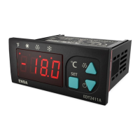
EDT2411A
Thank you for choosing temperature controllerENDA EDT2411A .
ENDA 2 A DIGITAL THERMOSTATEDT 411
35x77mm.
On-Off control.
Relay output for cooling or heating control.
Single NTC probe input.
Offset value can be entered for NTC input.
Compressor protection parameters can be entered.
In case of probe failure, output status can be set to
ON, OFF or periodic.
Upper and Lower setpoint value limits can be ed.adjust
Selectable “Smart Defrost” feature.
Defrosting duration and intervals can be adjusted.
6 Different warning tone selections.
Lower and upper alarm limit can be adjusted to depending
on set value.
Temperature unit can be selected C or F.° °
Digital input ;
E- xternal alarm
I- nitiate defrost
Transfer device parameter settings with ENDAKEY
N - o power-up required.
RS485 ModBus protocol communication feature (optional).
CE marked according to European Norms.
Ple
a
se
r
e
ad
th
is
do
cum
e
n
t
car
ef
ul
ly
be
f
o
r
e
u
s
in
g
t
h
is
p
r
o
duc
t
.
T
he
gu
a
r
a
ntee
wi
ll
be in
val
ida
t
e
d
i
f
the
dev
i
ce
i
s dam
a
g
ed
b
y n
ot
f
o
l
lo
w
i
n
g i
ns
t
r
uc
t
io
ns de
ta
i
le
d in
t
he
m
a
nu
a
l.
The
c
o
mpa
n
y sha
ll
n
o
t b
e
r
e
s
pon
sib
le
for
a
n
y
d
am
a
g
e
or l
os
s
e
s h
ow
ev
e
r
c
a
u
sed
,
wh
ic
h
m
a
y b
e e
xpe
ri
en
ce
d as
a
re
sul
t
of
t
h
e
i
nstall
at
io
no
r us
e
o
f
t
h
i
s
p
r
o
du
c
t.
CONNECTION DIAGRAM
ENDA EDT2411A is intended for installation in control panels. Make sure that the device is used
only for intended purpose. The electrical connections must be carried out by a qualified staff
and must be according to the relevant locally applicable regulations. During an installation, all of the cables
that are connected to the device must be free of electrical power. The device must be protected against
inadmissible humidity, vibrations, severe soiling and make sure that the operation temperature is not
exceeded. The cables should not be close to the power cables or components.
SUPPLY:
NOTE:
184-253V AC
50/60Hz 4VA
Line
Neutral
230V AC
Supply
Switch
Note:
Cable size: 1,5mm²
Fuse
F 100 mA
250V AC
Fuse should
be connected
1) Mains supply cords shall meet the requirements of
IEC 60227 or IEC 60245.
2) In accordance with the safety regulations, the power
supply switch shall bring the identification of the
relevant instrument and it should be easily
accessible by the operator.
1
2
Order Code : EDT2411A - - -
1 2
3
1 - Supply Voltage
230..... 230V AC ...
24........24V AC/DC
12........12V AC/DC
SM........9-30VDC / 7-24V AC
24V.......12V / 24V DC
2-Output
R......... 8A Relay output
P......... 20A Relay output
3 b - Mod us
RS..... RS-485 Modb... us Available
(Optional / Specify at order)
....Blank N/A
Holding screw
0.4-0.5Nm
Equipment is protected throughout
by DOUBLE INSULATION.
ENVIRONMENTAL CONDITIONS
Height
Max. 2000m
Ambient / torage emperature S T
Relative umidityH
0 ... +50°C/-40 ... 85°C (without icing)
Protection Class
According to EN60529; Front panel : IP65, Rear panel : IP20
Do not use the device in locations subject to corrosive and flammable gasses.
Supply oltageV
230V AC +%10 -%20, 50/60Hz ; 12V AC/DC ± %10 or 24V AC/DC ±%10
Power onsumptionC
Max. 5VA
2.5mm² screw-terminal connections
±1%
4 digits, 12.5mm, 7 segment LED (V2 Code : Blue Display)
Connection
Scale
Sensitivity
Accuracy
Time ccuracyA
Display
EMC
Safety Requirements
EN 61326-1: 2013
EN 61010-1: 2010 (Pollution degree 2, overvoltage category II)
ELECTRICAL CHARACTERISTICS
-60.0 ... +150.0°C (-76.0 ... +302.0°F)
0.1°C (Can be selected as 0.1 or .)ºC 1ºC
±1°C
CONTROL
Control ypeT
Single set-point control
On-Off control
Control lgorithmA
Hysteresis
Adjustable between 1 ... 20.0°C.
Life xpectancy for elayE R
OUTPUTS
HOUSING
Housing ypeT
Suitable for flush -panel mounting
Dimensions
W77xH35xD61mm
Weight
Approx. 190g (After packing)
Enclosure aterialM
Self extinguishing plastics.
While cleaning the device,solvents (thinner,benzine,acid etc.) or corrosive materials must not be used.
Relay Output
For EDT2411A-X-R ; Without load 30.000.000 mechanical;
250V AC, 8A resistive load 100.000 electrical operation.
For EDT2411A-X-P ; Without load 10.000.000 switching;
277V AC,20A (for resistive load) 100.000 electrical operation.
For EDT2411A-X-R ; Relay : NO+NC 250V AC,8A (resistive load),
1/2HP, 240V AC (inductive load)0.37KW
For EDT2411A-X-P ; Relay : NO 277V AC,20A (resistive load),
1/2HP, 250V AC (inductive load)0.37KW
Max. humidity 80% for temperatures up to 31°C decreasing linearly to
50% relative humidity at 40°C.
DIMENSIONS
Note:
1) Panel thickness should
be maximum 7mm.
2) If there is no 60mm free
space at the back side of
the device,it would be
difficult to remove it from
the panel.
Flush mounting
clamp
For removing mounting clamps:
- Push the flush-mounting
clamp in direction as shown1
in the figure below.Then,pull
out the clamp in direction .2
71,5mm
Panel cut-out
61mm 5mm
Flush mounting
clamp
Panel
Rubber
packing
2
Depth
77mm
1
1 2 3 4 5 6
7 8 9
10
ENDA INDUSTRIAL ELECTRONICS
SN: XXXXXXXXX
EDT24 1-230-R1
DIGITAL THERMOSTAT
11
12
COMPRESSOR
250V AC 8A
RESISTIVE LOAD
8 680407 702220
EDT2411A
SURAN Industrieelektronik
Dettinger Str. 9
D-72160 Horb a.N.
Tel.: +49 (0)7451 / 625 617 E-mail : info@suran-elektronik.de
Fax: +49 (0)7451 / 625 0650 Internet : www.suran-elektronik.de
english