Band Alarm With Inhibition
A1tP.= bAn.i.
ON
ON
OFF
OFF
Begining
of procedure
SV =Set point of CONT output
ASV = Set point of AL1 output
(ASV min. = 0, ASV max. = 300 )
Band alarm is possible
Band alarm is possible
Begining
of procedure
SV
SV
SV+ASV
SV+ASV
SV-ASV
SV-ASV
Holding screw
0.4-0.5Nm
Equipment is protected throughout
by DOUBLE INSULATION
2/4
ETCXXX-E-02-R-A3
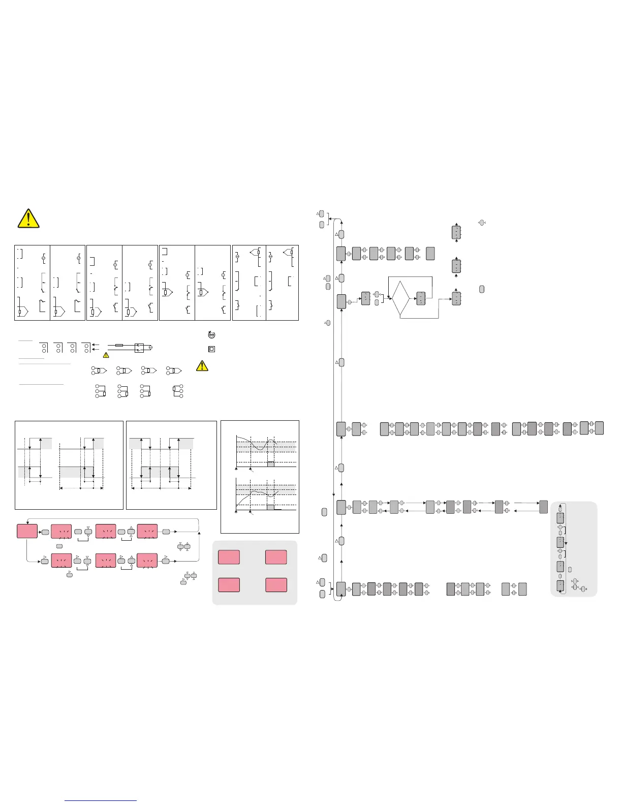
ALARM1 AND ALARM2 OUTPUT TYPES
CONNECTION DIAGRAM
ENDA ETC series are intended for installation in control panels. Make sure that the device is used only for intended purpose.
must be grounded on the instrument side. During an installation, all of the cables that are connected to the device must be free of energy.
The device must be protected against inadmissible humidity, vibrations, severe soiling and make sure that the operation temperature is not
exceeded. All input and output lines that are not connected to the supply network must be laid out as shielded and twisted cables. These
cables should not be close to the power cables or components. The installation and electrical connections must be carried on by a qualified
staff and must be according to the relevant locally applicable regulations.
The shielding
Logic output of the instrument is not electrically
insulated from the internal circuits. Therefore,
when using a grounding thermocouple, do not
connect the logic output terminals to the ground.
1) Mains supply cords shall meet the requirements
of IEC 60227 or IEC 60245.
2) In accordance with the safety regulation, the
power supply switch shall bring the identification of
the relevant instrument and it should be easily
accessible by the operator.
Note:
A1.tP.=indE
Independent Alarm
A1.tP.= DE.
Deviation Alarm
Band Alarm
A1.tP.= bAnd
A.StA.= Hi
A1.St.= boHi
A.StA.= Lo
A1.St.= biHi
ASV
SV
SV
SV
SV+ASV
SV+ASV
SV-ASV
OFF
OFF
OFF
OFF
OFF
OFF
-300
300
+300
300
ON
ON
ON
ON
ON
ON
SV = ASV = Set point of CONT output Set point of alarm output
(ASV min. =-300, ASV max. = +300)
(ASV min. = 0, ASV max. = +300)
(
ASV max = end of scale)
ASV min = beginning of scale
SV = ASV = Set point of CONT output Set point of AL1 output
a1.Hy. A1.Hy..
A1.Hy.
A1.Hy.
(
ASV max. = +30.0)
If ,inP = Pt..0 ASV min. = -30.0,
(If , inP = Pt..0 ASV min. = 0.0, ASV max. = +30.0)
MODIFICATION OF CONTROL AND ALARM SET POINTS
C.SEt
150
A1.sE.
250
C.SEt
150
A1.sE.
250
A1.sE.
249
First, press and hold key until the massage C.Set appears on the display. Then, the value is adjusted by using keys.
SET
CSET
SET
CSET
SET
CSET
SET
CSET
ASET
ASET
ASET
When CSET is released, it
returns to normal operation.
When ASET is released, it
returns to normal operation.
130
150
PV
PV
PV
PV
PVPV
SV
SV
C.SEt
149
PV
SV
SV
SV
SV
SV
First, press and hold key, alarm setpoint value appears on the display. Then, the value is adjusted by using keys.
If C.ot.S different from out1. Alarm1 and Alarm2 setpoint values can be adjusted in sequence when per press key.
.
ASET
ASET
SET
CSET
ASET
NOTE: The maximum of is the value of parameter and the minimum of it is the value of parameter.
If independent alarm is selected, A1.SE. and values can be adjusted between the limits of the full scale.
If deviation alarm is selected, A1.SE. and A2.SE. values can be adjusted between - and + .
If band alarm is selected, A1.SE. and A2.SE. values can be adjusted between 0 and +300.
C.SEt C.Hi.L. C.Lo.L.
A2.SE.
300 300
- - - -
- - - -
PFA
150
PSC
150
PV PV
PV
PV
SV SV
SV
SV
Error Messages
Temperature value is
higher than the scale
Temperature value is
lower than the scale
Temperature sensor
is broken or over temperature
Pt 100 or a sensor
line is short circuited
150
150
Pt 100
TC
TC
-
+
-
+
9
8
ETC9420
EUC9420
230V or 24V AC
Supply
Cable size: 1,5mm²
8
Pt 100
9
7
7
8
6
TC
-
+
-
+
9
8
-
+
-
+
8
7
ETC4420
ETC7420
ETC8420
ETC4420
EUC7420
EUC8420
TC
-
+
-
+
7
Pt 100
8
8
6
Switch
Fuse
F 100 mA 250V AC
Nötr
Faz
Fuse should
be connected
7
For J-K-T-S-R type thermocouple :
Use suitable compensation cables. Don’t use
jointed cables. Pay attention to the polarities
of the thermocouple cables as shown in the
figure right are connected to the.
For resistance thermometer :
When 2 wired Pt 100 is used, terminals that are
shown at the right of there must be short
circuited for each product.
10
9
184-253V AC
50/60Hz 7VA
SUPPLY :
SENSOR INPUT :
NOTE :
12
11
16
15
2
1
ETC4420
ETC7420
ETC8420
ETC9420
0-20mA or
4-20mA input
0-20mA or
4-20mA input
0-20mA or
4-20mA input
0-20mA or
4-20mA input
Pt 100
8
9
10
A1.tp.
IndE.
A2.tp.
IndE.
A1.St.
HI.
A2.St.
HI.
A1.P.e.
on
A2.P.e.
oFF
A1.Hy.
2
A2.Hy.
2
ALr.o.
ASET
ASET
Con.o.
Pb
4
C.oT.S.
Out1
S.S.T.S.
0
tý
4.0
td
1.00
Ct
20
P.SEt.
0
C.HyS.
2
C.StA.
HEAt
Pr.Er.
0
SET
CSET
SET
CSET
ASET
ASET
C.ot.S. = Type of control output
out1 = Out1 control output.
S.s.r = SSR control output.
S.S.t.S. = Soft Start timer set point value
This parameter indicates the time to reach set point
value when the device is first energized.
Adjustable between 0 and 250 minutes.
If 0 is selected, soft start feature will be enable and
the device reaches set point value quickly.
NOTE! Setting Pb = 0, soft start feature will be
disable.
Pb = Proportional band.
Adjustable between 0% and 100%
Setting Pb = 0% On-Off control is selected.
Ti = Integral time.
Adjustable between 0.0 and 100.0 minutes.
If ti = 0.0, integral effect is not used.
td = Derivative time.
Adjustable between 0.00 and 25.00
minutes.
Ct = Control period.
Adjustable between 1 and 250 seconds.
Setting Pb = 0 and C.ot.S.= Out1 this
parameter is not seen.
P.SEt. = The ratio of output power at the set
point.Adjustable between 0% and 100%.
If this parameter is set to 0, the output power
becomes 0 at the set point. If it is adjusted to 50%
output power becomes 50% at the set point. Using
this parameter the energy requirements of the
system is adjusted at the set point. So the set point
can be achieved by minimum fluctuations and in
the shortest time.Setting Pb = 0, this parameter is
not seen.
C.HYS. = Hysteresis of the control output.
Adjustable between 1 and 50 °C/F.
Adjustable between 0,1 and 50 ,if inp=Pt.0
Setting Pb = 0 this parameter is seen.
°C/F
C.StA. = Configuration of the control output.
C.StA. = HEAt means heating control.
Pr.Er. = This parameter is used to adjust the
control output during a sensor failure.
Adjustable between 0% and 100%.
If this parameter is adjusted to a value closer to the
energy requirements of the system at the set point,
process temperature is prevented to rise or drop to
dangerous levels.
A1.p.e. = State of Alarm1 output in the
case of sensor failure.
If A1.p.e.= On , the alarm output is
energised during the sensor failure.
If A1.p.e.= oFF, the alarm output is not
energized during the sensor failure.
A2.p.e. =
case of sensor failure.
If = , the alarm output is
energized during the sensor failure.
If A2.p.e.= oFF, the alarm output is not
energized during the sensor failure.
NOTE! If C.ot.S. = .out1, this
parameter is not seen.
State of Alarm2 output in the
A2.p.e. On
A1. =
output.
Hy. Hysteresis of the Alarm1
A2. =
output.
Adjustable between 1 and 50°C.
NOTE! If C.ot.S. =.out1, this
parameter is not seen.
Hy. Hysteresis of the Alarm2
A1.tP. =
Four kinds of functions can be selected.
indE. = Independent
dE. = Deviation
bAnd = Band
bAn.i. = Band with inhibition
Function of Alarm1 output.
A2.tP. =
Four kinds of functions can be selected.
indE. = Independent
dE. = Deviation
bAnd = Band
bAn.i. = Band with inhibition
NOTE! If C.ot.S. = .out1, this
parameter is not seen.
Function of Alarm2 output.
A1.St. =
If independent or deviation alarm is
selected, this parameter can be Lo.
and Hi.. For Lo. alarm output is
energized below the alarm set point. For
Hi. alarm output is energized above the
alarm set point. If band alarm is selected,
this parameter can be bIHI or boHI.
bIHI means alarm is activated inside the
band.boHI means alarm is activated
outside the band.
The state of Alarm1.
A2.St. =
If independent or deviation alarm is
selected, this parameter can be Lo. and
Hi. For Lo. alarm output is energised
below the alarm set point. For Hi. alarm
output is energized above the alarm set
point. If band alarm is selected, this
parameter can be bIHI or boHI.
bIHI means alarm is activated inside the
band. boHI means alarm is activated
outside the band.
The state of Alarm2.
ASET
SET
SECU.
ASET
ASET
S.cod.
0
A.Con.
P.yES
A.ALr.
P.yES
A.CNF.
P.yES
A.tun.
yES
SET
CSET
ASET
Yes
25
P.SE.t.
SET
CSET
S.cod. =
code.
It should be 666.
Security menu access
A.Con. = CoN.o
menu access level code.
nonE = Invisible
P.yES = Modification can be done.
Parameters of
A.ALr.. = ALr.o
menu access level code.
nonE = Invisible
P.yES = Modification can be done.
Parameters of
A.CNf. = ConF.
menu access level code.
nonE = Invisible
P.yES = Modification can be done.
Parameters of
A.tun. = S.tun.
menu access level code.
no = Invisible
yES = Self tune can be done.
Parameters of
Before starting sef-tune
procedure, be sure A.tun
parameter is YES
in the SECU menu.
After
PID is
calculated
Press any
key to
deactivate
the self-
tune
procedure.
While holding key, run message flashes. Then when key is
pressed,
self tune mode is entered if there is no probe failure. If process value is
Appropriate to begin self tune, rEdY. message flashes. Then press any key
to see Pid.t. message and self tune procedure begins.Process value must
be equal or lower than 60%of the setpoint to begin self tune procedure. If not,
tE.Hi. message flashes and device waits to decrease appropriate
temperature to begin self tune. Then rEdY. message flashes and press any
key to begin sellf tune procedure.
Before self tune procedure, A.tun. parameter must be selected yES from the
SECU menu.If self tune is achieved A.tun. parameter becomes no
automatically and S.tun menu is canceled. Before self tune procedure,
temperature setpoint value should be adjusted. When self tune procedure
begins with no failure, Pid.t. message flashes and remains during the
calculation of PID parameters. When PID parameters are calculated, P.SE.t.
message flashes. Then the device heats until setpoint value according to PID
parameters and calculates the energyrequirement for stable temperature and
writes P.SE.t. parameter as %and run mode enters.
If any key is pressed while Pid.t. message flashes, self tune prosedure is
deactivated before calculation of PID parameters. If any key is pressed while
P.SE.t. message flashes, then self tune prosedure is deactivated as PID
parameters are calculated and P.SE.t. parameter is done 0.
Entering from the programming mode to the run mode:
If no key is pressed within 20 seconds during programming mode, the data is stored automatically and the run mode is entered.
Alternatively, the same function occurs first pressing key and then pressing keys together.
If key is pressed while holding key, the programming mode is enabled.
ConF.
ýnP.
FE.cn.
S.tun.
CSET
ASET
SET
CSET
S.Str.
run
No
70
TE.Hý.
25
REdY.
Process
value is equal or lower
than 60%of the set
point ?
Press
any key
d.Pnt.
0
d.Pnt. =Decimal point for mA inputs.
Adjusable between 0 and 2.
NOTE! If inP is selected one of the mA input types, this parameter is
seen.
C.Hi.L.
600
C.Lo.L.
0
oFFS.
0
A1.H.L.
600
A2.H.L.
600
A1.L.L.
0
A2.L.L.
0
fL.Co.
5
inP. = Type of input and scale.
Pt = Pt 100 -200 to +600°C
Pt.0 = Pt 100 -99.9 to +300.0°C
FE.cn. = J (Iron vs. Copper-Nickel) 0 to +600°C
nc.nA. = K (Nickel-Cr.vs. Nickel-Alum.) 0 to +1200°C
c.cn. = T (Copper vs. Copper-Nickel) 0 to +400°C
P10.r. = S (Platinum-10%Rhodium vs. Pt.) 0 to +1600°C
P13.r. = R (Platinum-13%Rhodium vs. Pt.) 0 to +1600°C
C.Hi.L. =
If InP. or UnIt. parameters are changed, the maximum value of the
C.Hi.L. parameter changes to the maximum scale value of the selected
Set point upper limit.
C.LoL. =
If InP. or UnIt. parameters are changed, the minimum value of the
C.Lo.L. parameter changes to the minimum scale value of the selected
input. The maximum value is the value of C.Hi.L. parameter.
Set point lower limit.
oFFS. =
Offset value is added to the measurement value.
Offset value.
UnIt =
Selectable as °C or °F.
Note : If the temperature unit is changed, the value of the UPL., Lol.,
A.UP.L., A.Lo.L. Parameters changes automatically.
The temperature unit.
A1.H.L
If InP. or UnIt. parameters are changed, the maximum value of the
A1.H.L. parameter changes to the maximum scale value of the selected
input type. Minimum of A1.H.L. parameter is the value of A1.L.L.
= Alarm1 value upper limit.
A2.H.L
If InP. or UnIt. parameters are changed, the maximum value of the
A2.H.L. parameter changes to the maximum scale value of the selected
input type. Minimum of A2.H.L. parameter is the value of A2.L.L.
parameter.
= Alarm2 value upper limit.
A1.L.L. =
If InP. or UnIt. parameters are changed, the minimum value of the
A1.L.L. parameter changes to the minimum scale value of the selected
Alarm1 value lower limit.
A2.L.L. =
If InP. or UnIt. parameters are changed, the minimum value of the
A2.L.L. parameter changes to the minimum scale value of the selected
input type. The maximum value is the value of A2.H.L. parameter.
Alarm2 value lower limit.
fL.Co. = Coefficient of digital filter.
Filter for display value.
Adjustable between 1 and 32. If this parameter is 1, digital filter runs most
quick. If the parameter is 31, the filter run most slow. The value of
parameter should be increased in interference.
U.SC.L. = Lower scale value for ma inputs.
Adjusable between -999 and the (U.SC.H. -100)
NOTE! If inP is selected one of the mA input types, this parameter is
seen.
d.adr.
1
baud
oFF
d.adr. = Device address.
Adjusable between 1 and 247. Difference addresses should be selected
for every device.
Baud= Modbus baud rate.
Selectable 1200, 2400, 4800 and 9600.
If baud= off, Modbus communication will be disable.
U.SC.H.
4000
U.SC.H. = Upper scale value for mA inputs.
Adjusable between (U.SC.L. +100) and 4000.
NOTE! If inP is selected one of the mA input types, this parameter is
seen.
25
Pýd.t.
ASET
C.HyS.
6
SET
CSET
SET
CSET
Modification Of Parameter Diagram
C.HyS.
5
C.HyS.
6
SET
CSET
SET
CSET
SET
CSET
C.HyS.
6
When holding key, the value of parameter flashes and using
keys the requested value can be adjusted.
If key is pressed and held 0.6 seconds, the value of the selected
parameter changes rapidly. If waited enough,the value increases 100 at each
step. After 1 second following the release of the key, initial condition is
returned.The same procedure is valid for the decrement key.
3/4
ETCXXX-E-02-R-A3
U.sC.l.
-999
Unit.
°C
15
16
17
18
19
20
21
10
11
12
11
12
13
14
15
16
17
15
16
17
18
19
20
21
10
11
12
11
12
13
14
15
16
17
8
9
10
ETC7420-230VAC
ETC7420-24VAC
ETC8420-230VAC
ETC9420-230VAC
ETC8420-24VAC
ETC9420-24VAC
8
9
10
8
9
10
11
12
13
14
3
4
5
ETC4420-230VAC
8
9
10
11
12
13
14
3
4
5
ETC4420-24VAC
-
-
+
+
CONT./AL2
Al1
AC 250V 2A
RESISTIVE
LOAD
AC 250V 2A
RESISTIVE
LOAD
230V AC
+10% -20%
50/60Hz 5VA
TC
Pt 100
RS-485 COM.
RS- 485
SSR
OUT
B
+
-
2
1
A
6
7
15
1
2
6
7
15
1
2
3
4
5
6
7
1
2
3
4
5
6
7
1
2
3
4
5
6
7
8
9
13
14
1
2
3
4
5
6
7
8
9
13
14
SSR
OUT
+
-
-
+
TC
Pt 100
CONT./AL2
AC 250V 2A
RESISTIVE
LOAD
Al1
AC 250V 2A
RESISTIVE
LOAD
24V AC ±10%
50/60Hz 7VA
-
+
RS-485
COM.
RS- 485
SSR
OUT
A
B
+
-
230V AC
+10% -20%
50/60Hz 7VA
CONT./AL2
AC 250V 2A
RESISTIVE
LOAD
AL1
AC 250V 2A
RESISTIVE
LOAD
TC
+
-
Pt 100
SSR
OUT
+
-
TC
+
-
Pt 100
CONT./AL2
AC 250V 2A
RESISTIVE
LOAD
AL1
AC 250V 2A
RESISTIVE
LOAD
24V AC ±10%
50/60Hz 5VA
-
+
RS-485
COM.
RS- 485
A
B
SSR
OUT
+
-
TC
+
-
Pt 100
230V AC
+10% -20%
50/60Hz 7VA
CONT./AL2
AC 250V 2A
RESISTIVE
LOAD
AL1
AC 250V 2A
RESISTIVE
LOAD
SSR
OUT
+
-
TC
+
-
Pt 100
CONT./AL2
AC 250V 2A
RESISTIVE
LOAD
AL1
AC 250V 2A
RESISTIVE
LOAD
24V AC ±10%
50/60Hz 7VA
8
9
10
11
12
13
14
3
4
5
2
1
6
7
15
230V AC
+10% -20%
50/60Hz 7VA
CONT./AL2 OUT
AC 250V 2A
RESISTIVE
LOAD
AL1
AC 250V 2A
RESISTIVE
LOAD
+
-
Pt 100
TC
SSR
OUT
+
-
-
+
RS-485 COM.
RS- 485
A
B
8
9
10
11
12
13
14
3
4
5
2
1
6
7
15
CONT./AL2 OUT
AC 250V 2A
RESISTIVE
LOAD
AL1
AC 250V 2A
RESISTIVE
LOAD
+
-
Pt 100
TC
SSR
OUT
+
-
24V AC ±10%
50/60Hz 7VA
 Loading...