SET
PRG
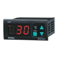
ETC1311
ENDA
OUT
°C
Technical Specifications
Thank you for choosing ENDA ETC1311 temperature controller.
* 35 x 77mm sized.
* On-Off control.
* J, K, Pt100 or Pt1000 input.
* Temperature compensation.
* In the case of probe failure, heating can be
selected on, off or periodical running.
* Upper and lower limits of the setpoint can be
adjusted.
* Set value can be adjusted by using single key.
* CE marked according to European Norms.
Connection Diagram
ENDA ETC1311 is intended for installation in control panels. Make sure that the device is
used only for intended purpose. The electrical connections must be carried out by a
qualified staff and must be according to the relevant locally applicable regulations. During
an installation, all of the cables that are connected to the device must be free of electrical
power. The device must be protected against inadmissible humidity, vibrations, severe
soiling and make sure that the operation temperature is not exceeded. The cables should
not be close to the power cables or components.
1/2
SÝSEL MÜHENDÝSLÝK ELEKTRONÝK SAN. VE TÝC. A.Þ.
Yukarý Dudullu Barbaros Cad. Kutup Sok. No:20 34775 - ÜMRANÝYE/ÝSTANBUL/TÜRKÝYE
Tel : +90 216 499 46 64 Pbx. Fax : +90 216 365 74 01
url : www.enda.com.tr
ETC1311-E-10-R
Holding screw 0.4-0.5Nm
Equipment is protected throughout
by DOUBLE INSULATION.
ENDA ETC1311 DIGITAL THERMOSTAT
ENVIRONMENTAL CONDITIONS
Height
Max. 2000m
80 , up to 40% 31°C decreasing linearly 50% at °C
Ambient/storage temperature
Max. relative humidity
0 ... +50°C/-25 ... 70°C (with no icing)
Rated pollution degree
According to EN 60529 Front panel : IP65
Rear panel : IP20
Do not use the device in locations subject to corrosive and flammable gasses.
Supply voltage
230V AC +10% -20%, 50/60Hz or 24V AC 10%, 50/60Hz or 12V AC 10%, 50/60Hz or
optional 9-30V DC / 7-24V AC 10% SMPS module.
± ±
±
Power consumption
Max. 4VA
2.5mm² screw-terminal connections.
3 digits, 14.2mm, 7 segment red LED
Wiring
Scale
Accuracy
Indicator
EMC
Safety requirements
The device is designed to operate in controlled electromagnetic environment)
EN 61326-1: 1997, A1: 1998, A2: 2001 (Performance criterion B is satisfied for EMC tests.
EN 61010-1: 2001 (Pollution degree 2, overvoltage category II)
ELECTRICAL CHARACTERISTICS
0 .... +600°C for Fe-Const (J) and NiCr-Ni (K). -100 .... +600°C for Pt100 and Pt1000
± 0.5% (of full scale) ±1 digit
OUTPUT
HEAT OUT
For Relay: 250VAC, 8A( ), NO+NC,
For ETC1311-XX-XX-P ; Relay: 240VAC, 16A(for resistive load), NO or 12VDC 20mA logic out.
ETC1311-XX-XX ; for resistive load
For ETC1311-XX-XX ;
For ETC1311-XX-XX-P ; Mechanical 30.000.000; Electrical 30.000 operation.
Mechanical 30.000.000; Electrical 100.000 operation.
Life expectancy for relay
CONTROL
Control type
Single-setpoint control
On-Off control
Control algorithm
Hysteresis
Adjustable between 1 ... 20°C.
HOUSING
Housing type
Suitable for flush-panel mounting.
Dimensions
W77xH35xD71mm
Weight
Approx. 198g (A ) fter packing
Enclosure material
Self extinguishing plastics
While cleaning the device, solvents (thinner, benzine, acid etc.) or corrosive materials must not be used.
4
5
SUPPLY:
NOTE:
184-253V AC
50/60Hz 4VA
Line
Neutral
230V AC
Supply
Switch
Note:
Cable size: 1,5mm²
Fuse
F 100 mA
250V AC
Fuse should
be connected
1) Mains supply cords shall meet the requirements of
IEC 60227 or IEC 60245.
2) In accordance with the safety regulations, the power
supply switch shall bring the identification of the
relevant instrument and it should be easily
accessible by the operator.
Order Code : ETC1311- - -
1 - Input
FE.....Fe-Const (J)
RT.....Pt100
PT.....Pt1000
K.......NiCr-Ni (K)
2 - Supply Voltage
230VAC...230V AC
24VAC.....24V AC
12VAC.....12V AC
SM...........9-30V DC / 7-24V AC
3 - Output
P......... Relay-16A
None...Relay-8A
SSR....Logic output
Pl
ea
se
re
a
d
t
hi
s d
o
cu
m
en
t
ca
ref
ul
ly
b
ef
or
e
u
si
ng
t
hi
s
pr
o
du
ct.
Th
e g
ua
ra
nt
e
e
w
i
l
l be
i
nv
al
id
at
ed
i
f
t
h
e
de
vic
e
i
s da
mag
e
d
b
y no
t
f
o
l
lo
w
i
ng
i
n
stru
ct
i
o
ns
d
et
ai
le
d
in
the
m
a
nu
a
l. T
h
e
c
omp
an
y
sh
a
l
l
no
t
be
re
sp
on
si
b
l
e
fo
r a
ny
d
a
ma
g
e
o
r
lo
ss
es
h
ow
e
ve
r
c
a
u
s
ed
,
whi
ch
m
ay
be
ex
p
e
r
ie
n
ced
as
a
r
es
ul
t
o
f
t
he
i
ns
ta
ll
at
io
n
o
r u
se
o
f thi
s pr
od
u
c
t.
1 2 3
SET
PRG
ETC1311
ENDA
OUT
°C
SN: XXXXXXXXX
ETC1311-RT-12VAC
DIGITAL THERMOSTAT
ENDA INDUSTRIAL ELECTRONICS
HEAT OUT
250V AC 8A
RESISTIVE LOAD
1 2 3 4 5 6
7 8 9
10
11 12
12V AC ±10%
50/60Hz 4VA
Pt100
SN: XXXXXXXXX
ETC1311-K-230VAC
DIGITAL THERMOSTAT
ENDA INDUSTRIAL ELECTRONICS
HEAT OUT
250V AC 8A
RESISTIVE LOAD
1 2 3 4 5 6
7 8 9
10
11 12
230V AC +10% -20%
50/60Hz 4VA
K (NiCr-Ni)
-
+
SN: XXXXXXXXX
1 2 3
ETC1311-FE-SM-P
DIGITAL THERMOSTAT
ENDA INDUSTRIAL ELECTRONICS
HEAT OUT
240V AC 16A
RESISTIVE LOAD
9-30V DC / 7-24V AC
±10% 4VA
J (Fe-CuNi)
-
+
4 5 6
7 8 9
10
11 12
Panel cut-out
Dimensions
Note :
1) Panel thickness
should be maximum
7 mm.
2) If there is no 60mm
free space at the back
side of the device, it
would be difficult to
remove it from the
Panel.
71mm
29mm
Flush mounting
clamp
For removing mounting clamps:
Push the flush-mounting
clamp in direction 1 as shown
in the figure below. Then, pull
out the clamp in direction 2.
1
35mm
77mm
Flush mounting
clamp
Depth
Panel
2
71mm
5mm
Rubber
packing
SN: XXXXXXXXX
ETC1311-K-230VAC
DIGITAL THERMOSTAT
ENDA INDUSTRIAL ELECTRONICS
HEAT OUT
250V AC 8A
RESISTIVE LOAD
1 2 3 4 5 6
7 8 9
10
11 12
230V AC +10% -20%
50/60Hz 4VA
K (NiCr-Ni)
-
+