A1.tp.
ýndE.
A2.tp.
ýndE.
A1.St.
Hý.
A2.St.
Hý.
A1.P.e.
oFF
A2.P.e.
oFF
A1.Hy.
2
A2.Hy.
2
ALr.o.
ConF.
ýnP.
FE.cn.
C.Hi.L.
600
C.Lo.L.
0
oFFS.
0
A1.H.L.
600
A2.H.L.
600
A1.L.L.
0
A2.L.L.
0
ASET
ASET
Con.o.
Pb
4
C.oT.S.
Out1
S.S.T.S.
0
tý
4.0
td
1.00
Ct
20
P.SEt.
0
C.HyS.
2
C.StA.
HEAt
Pr.Er.
0
SET
CSET
SET
CSET
ASET
ASET
fL.Co.
5
S.tun.
ASET
SET
CSET
ASET
SECU.
ASET
ASET
ASET
S.cod.
0
A.Con.
P.yES
A.ALr.
P.yES
A.CNF.
P.yES
A.tun.
yES
SET
CSET
ASET
SET
CSET
S.Str.
run
25
Pýd.t.
Yes
No
25
REdY.
70
TE.Hý.
25
P.SE.t.
SET
CSET
d.adr.
1
baud
off
C.HyS.
6
SET
CSET
SET
CSET
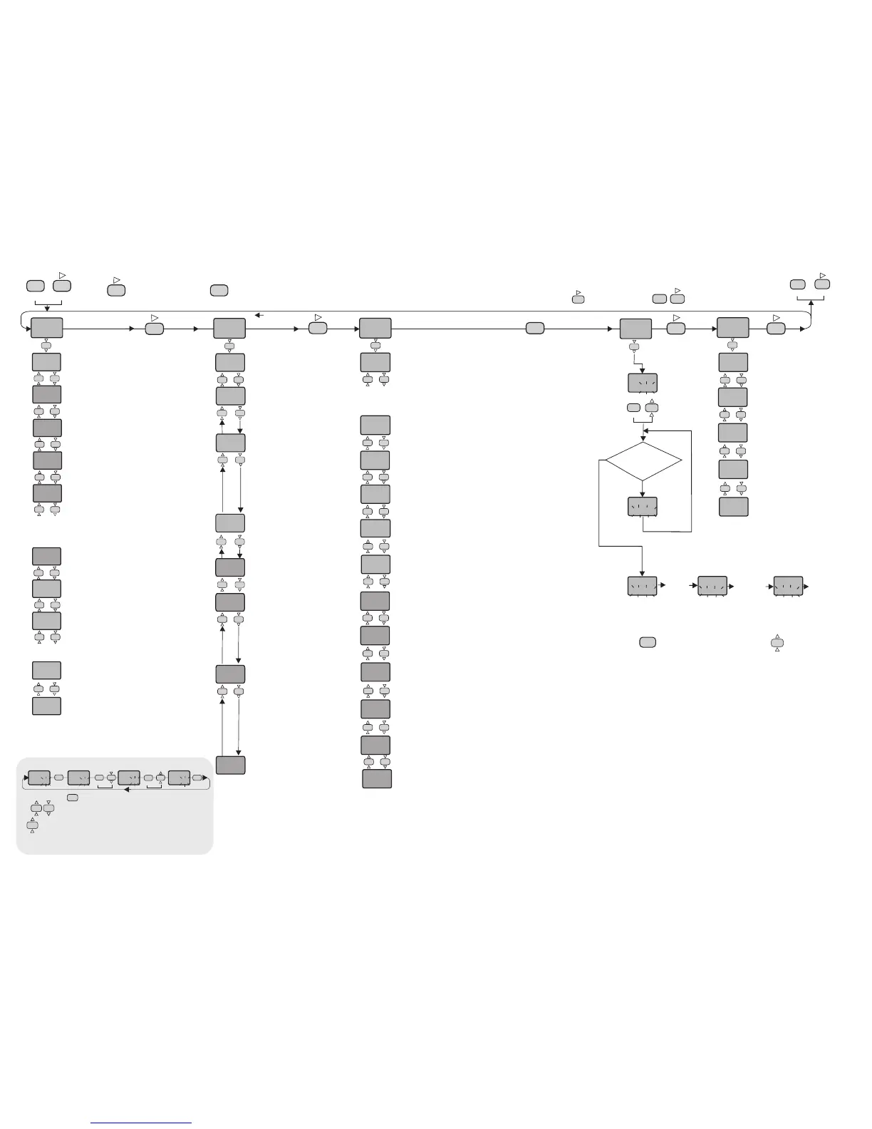
Modification Of Parameter Diagram
C.HyS.
5
C.HyS.
6
SET
CSET
SET
CSET
SET
CSET
C.HyS.
6
2/4
ETC4420-E-02-R
C.ot.S. = Type of control output
Out1 = Out1 is control output.
S.s.r = SSr control output.
Out1 = Alarm2 output.
S.S.t.S. = Soft Start timer set point value
This parameter indicates the time to reach set point value
when the device is first energized.
Adjustable between 0 and 250 minutes.
If 0 is selected, soft start feature will be enable and the
device reaches set point value quickly.
NOTE! Setting Pb = 0, soft start feature will be disable.
Pb = Proportional band.
Adjustable between 0% and 100%
Setting Pb = 0% On-Off control is selected.
Ti = Integral time.
Adjustable between 0.0 and 100.0 minutes.
If ti = 0.0, integral effect is not used.
Setting Pb = 0 this parameter is not seen.
td = Derivative time.
Adjustable between 0.00 and 25.00 minutes.
If td = 0.00, derivation effect is not used.
Setting Pb = 0 this parameter is not seen.
Ct = Control period.
Adjustable between 1 and 250 seconds.
Setting Pb = 0 and C.ot.S.= Out1 this parameter is
not seen.
P.SEt. = The ratio of output power at the set
point.Adjustable between 0% and 100%.
If this parameter is set to 0, the output power becomes 0
at the set point. If it is adjusted to 50% output power
becomes 50% at the set point. Using this parameter the
energy requirements of the system is adjusted at the set
point. So the set point can be achieved by minimum
fluctuations and in the shortest time.Setting Pb = 0, this
parameter is not seen.
C.HYS. = Hysteresis of the control output.
Adjustable between 1 and 50 °C/F.
Setting Pb = 0 this parameter is seen.
C.StA. = Configuration of the control output.
C.StA. = HEAt means heating control.
C.StA. = cooL means cooling control.
Pr.Er. = This parameter is used to adjust the control
output during a sensor failure.
Adjustable between 0% and 100%.
If this parameter is adjusted to a value closer to the
energy requirements of the system at the set point,
process temperature is prevented to rise or drop to
dangerous levels.
A1.p.e. = State of Alarm1 output in the
case of sensor failure.
If A1.p.e.= On , the alarm output is
energized during the sensor failure.
If A1.p.e.= oFF, the alarm output is not
energized during the sensor failure.
A2.p.e. =
case of sensor failure.
If = , the alarm output is
energized during the sensor failure.
If A2.p.e.= oFF, the alarm output is not
energized during the sensor failure.
NOTE! If C.ot.S. = .out1, this
parameter is not seen.
State of Alarm2 output in the
A2.p.e. On
A1. =
output.
Adjustable between 1 and 50°C.
Hy. Hysteresis of the Alarm1
A2. =
output.
Adjustable between 1 and 50°C.
NOTE! If C.ot.S. =.out1, this
parameter is not seen.
Hy. Hysteresis of the Alarm2
A1.tP. =
Four kinds of functions can be selected.
indE. = Independent
dE. = Deviation
bAnd = Band
bAn.i. = Band with inhibition
Function of Alarm1 output.
A2.tP. =
Four kinds of functions can be selected.
indE. = Independent
dE. = Deviation
bAnd = Band
bAn.i. = Band with inhibition
NOTE! If C.ot.S. = .out1, this
parameter is not seen.
Function of Alarm2 output.
A1.St. =
If independent or deviation alarm is
selected, this parameter can be Lo. and
Hi. For Lo. alarm output is energized
below the alarm set point. For Hi. alarm
output is energized above the alarm set
point. If band alarm is selected, this
parameter can be bIHI or boHI. bIHI
means alarm is activated inside the
band.boHI means alarm is activated
outside the band.
The state of Alarm1.
A2.St. =
If independent or deviation alarm is
selected, this parameter can be Lo.
and Hi. For Lo. alarm output is
energized below the alarm set point. For
Hi. alarm output is energized above the
alarm set point. If band alarm is selected,
this parameter can be bIHI or boHI.
bIHI means alarm is activated inside
the band. boHI means alarm is
activated outside the band.
NOTE! If C.ot.S. = .out1, this
parameter is not seen.
The state of Alarm2.
inP. = Type of input and scale.
Pt = Pt 100 -200 to +600°C
Pt.0 = Pt 100 -99.9 to +300.0°C
FE.cn. = J (Iron vs. Copper-Nickel) 0 to +600°C
nc.nA. = K (Nickel-Cr.vs. Nickel-Alum.) 0 to +1200°C
c.cn. = T (Copper vs. Copper-Nickel) 0 to +400°C
P10.r. = S (Platinum-10%Rhodium vs. Pt.) 0 to +1600°C
P13.r. = R (Platinum-13%Rhodium vs. Pt.) 0 to +1600°C
Note : If the selected input type is changed, the value of C.Hi.L, C.Lo.L ,
A.Hi.L., A.Lo.L. parameters changes automatically.
C.Hi.L. =
If InP. or UnIt. parameters are changed, the maximum value of the C.Hi.L.
parameter changes to the maximum scale value of the selected input. The
minimum value is the value of C.Lo.L. parameter.
Set point upper limit.
C.LoL. =
If InP. or UnIt. parameters are changed, the minimum value of the C.Lo.L.
parameter changes to the minimum scale value of the selected input. The
maximum value is the value of C.Hi.L. parameter.
Set point lower limit.
oFFS. =
Offset value is added to the measurement value.
Adjusted between -99 and +99°C.The normal value is 0.
Offset value.
UnIt =
Selectable as °C or °F.
Note : If the temperature unit is changed, the value of the UPL., Lol., A.UP.L.,
A.Lo.L. Parameters changes automatically.
NOTE! IfInp parameter is selected TC or Pt100, this parameter is seen.
The temperature unit.
A1.H.L
If InP. or UnIt. parameters are changed, the maximum value of the A1.H.L.
parameter changes to the maximum scale value of the selected input type.
Minimum of A1.H.L. parameter is the value of A1.L.L. parameter.
= Alarm1 value upper limit.
A2.H.L
If InP. or UnIt. parameters are changed, the maximum value of the A2.H.L.
parameter changes to the maximum scale value of the selected input type.
Minimum of A2.H.L. parameter is the value of A2.L.L. parameter.
NOTE! If C.ot.S. = .out1, this parameter is not seen.
= Alarm2 value upper limit.
A1.L.L. =
If InP. or UnIt. parameters are changed, the minimum value of the A1.L.L.
parameter changes to the minimum scale value of the selected input type. The
maximum value is the value of A1.H.L. parameter.
Alarm1 value lower limit.
A2.L.L. =
If InP. or UnIt. parameters are changed, the minimum value of the A2.L.L.
parameter changes to the minimum scale value of the selected input type. The
maximum value is the value of A2.H.L. parameter.
Alarm2 value lower limit.
fL.Co. = Coefficient of digital filter.
Filter for display value.
Adjustable between 1 and 32. If this parameter is 1, digital filter runs most
quick. If the parameter is 31, the filter run most slow. The value of parameter
should be increased in interference.
d.adr. = Device address.
Adjusable between 1 and 247. Difference addresses should
be selected for every device.
Baud= Modbus baud rate.
Selectable 1200, 2400, 4800 and 9600.
If baud= off, Modbus communication will be disable.
S.cod. =
It should be 666.
Security menu access code.
A.Con. = CoN.o
access level code.
nonE = Invisible
P.yES = Modification can be done.
P. no = Only visible.
Parameters of menu
A.ALr.. = ALr.o
access level code.
nonE = Invisible
P.yES = Modification can be done.
P. no = Only visible.
Parameters of menu
A.CNf. = ConF.
access level code.
nonE = Invisible
P.yES = Modification can be done.
P. No = Only visible.
Parameters of menu
A.tun. = S.tun.
access level code.
no = Invisible
yES = Self tune can be done.
Parameters of menu
Before starting sef-tune
procedure, be sure A.tun
parameter is YES
in the SECU menu.
Process
value is equal or lower
than 60%of the set
point ?
After
PID is
calculated
Press
any key
Press any
key to
deactivate
the self-tune
procedure.
While holding key, run message flashes. Then when key is pressed,
self tune mode is entered if there is no probe failure. If process value is Appropriate to
begin self tune, rEdY. message flashes. Then press any key to see Pid.t. message
and self tune procedure begins.Process value must be equal or lower than 60%of the
setpoint to begin self tune procedure. If not, tE.Hi. message flashes and device waits
to decrease appropriate temperature to begin self tune. Then rEdY. message flashes
and press any key to begin sellf tune procedure.
Before self tune procedure, A.tun. parameter must be selected yES from the SECU
menu.If self tune is achieved A.tun. parameter becomes no automatically and S.tun
menu is canceled. Before self tune procedure, temperature setpoint value should be
adjusted. When self tune procedure begins with no failure, Pid.t. message flashes
and remains during the calculation of PID parameters. When PID parameters are
calculated, P.SE.t. message flashes. Then the device heats until setpoint value
according to PID parameters and calculates the energy requirement for stable
temperature and writes P.SE.t. parameter as %and run mode enters.
If any key is pressed while Pid.t. message flashes, self tune prosedure is deactivated
before calculation of PID parameters. If any key is pressed while P.SE.t. message
flashes, then self tune prosedure is deactivated as PID parameters are calculated and
P.SE.t. parameter is done 0.
Entering from the programming mode to the run mode:
If no key is pressed within 20 seconds during programming mode, the data is stored automatically and the run mode is entered.
Alternatively, the same function occurs first pressing key and then pressing keys together.
If key is pressed while holding key, the programming mode is enabled.
When holding key, the value of parameter flashes and using
keys the requested value can be adjusted.
If key is pressed and held 0.6 seconds, the value of the selected
parameter changes rapidly. If waited enough,the value increases 100 at each step.
After 1 second following the release of the key, initial condition is returned.The
same procedure is valid for the decrement key.
Unit.
°C
 Loading...