SÝSEL MÜHENDÝSLÝK ELEKTRONÝK SAN. VE TÝC. A.Þ.
Yukarý Dudullu Barbaros Cd. Kutup Sok. No:20 34775 - ÜMRANÝYE/ÝSTANBUL-TÜRKÝYE
Tel : +90 216 499 46 64 Pbx. Fax : +90 216 365 74 01
url : www.enda.com.tr
4/4
ETC4420-E-02-R
Logic output of the instrument is not electrically
insulated from the internal circuits. Therefore,
when using a grounding thermocouple, do not
connect the logic output terminals to the ground.
1) Mains supply cords shall meet the requirements
of IEC 60227 or IEC 60245.
2) In accordance with the safety regulations, the
power supply switch shall bring the identification of
the relevant instrument and it should be easily
accessible by the operator.
Note
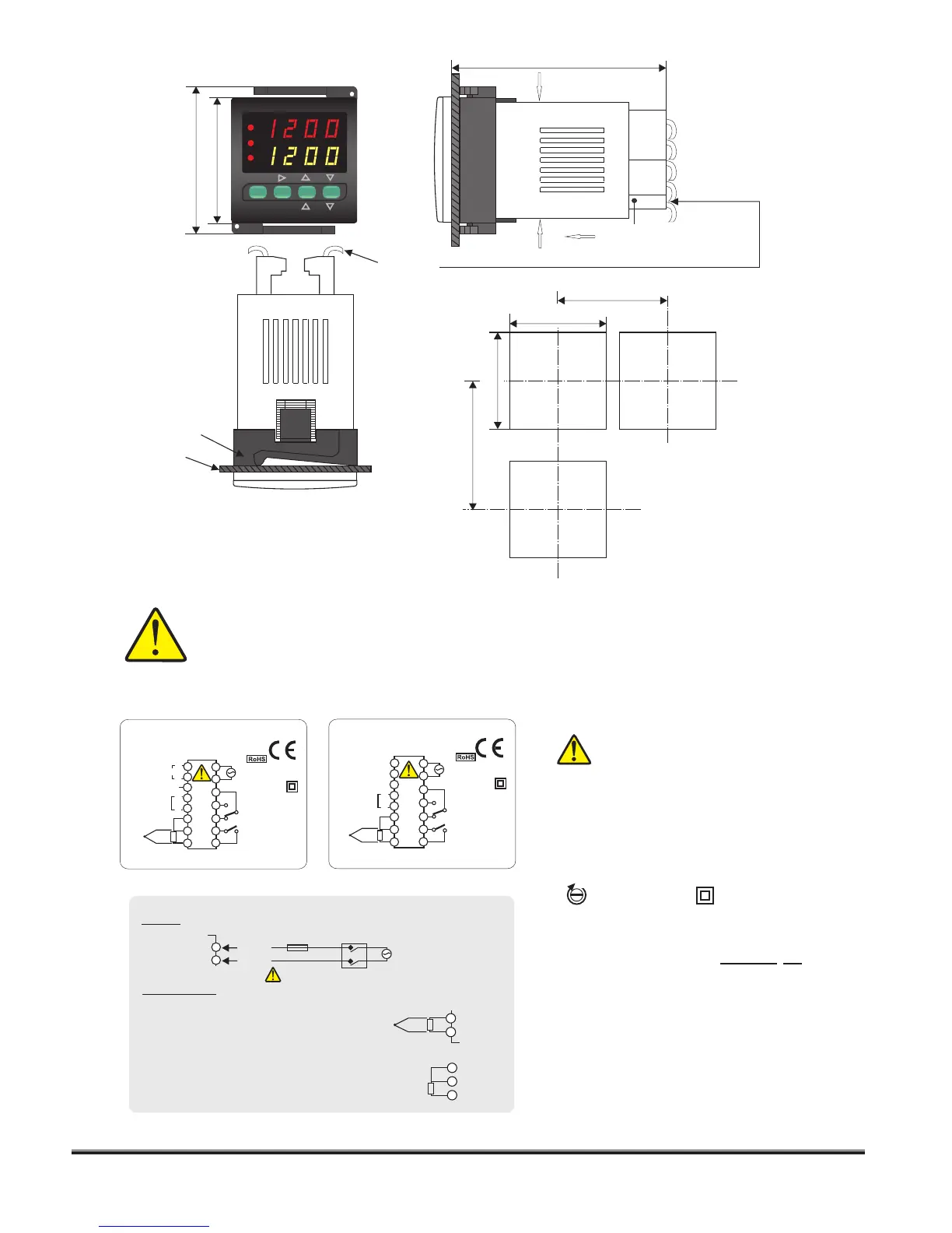
Holding screw
0.4-0.5Nm
Equipment is protected throughout
by DOUBLE INSULATION.
Note 1) While panel mounting, additional distance required for
connection cables should be considered.
2) Panel thickness should be maximum 9mm.
3) If there is no 100mm free space at back side of the device,
it would be difficult to remove it from the panel.
ENDA ETC4420 is intended for installation in control panels. Make sure that the device is used only for intended
purpose. The shielding must be grounded on the instrument side. During an installation, all of the cables that are
connected to the device must be free of energy. The device must be protected against inadmissible humidity,
vibrations, severe soiling and make sure that the operation temperature is not exceeded. All input and output lines
that are not connected to the supply network must be laid out as shielded and twisted cables. These cables should
not be close to the power cables or components. The installation and electrical connections must be carried on by
a qualified staff and must be according to the relevant locally applicable regulations.
For J-K-T-S-R type thermocouple :
Use suitable compensation cables. Don't use
jointed cables. Pay attention to the polarities of the
thermocouple cables as shown in the figure right
are connected to the .
For resistance thermometer :
When 2 wired Pt 100 is used, terminals 6 and 7 must
be short circuited.
NOTE :
Fuse should
be connected.
184-253V AC
or 99-121V AC
50/60Hz 5VA
230V or 24V AC
Supply
switch
Cable size: 1,5mm²
Fuse
F 100 mA
250V AC
Neutral
Line
SUPPLY :
SENSOR INPUT :
10
9
TC
-
+
-
+
7
8
6
7
8
Pt 100
48mm
51mm
80mm
45 mm
+0.6
45 mm
+0.6
58mm
Panel cut-out
Panel
Flush mounting
clamp
CONNECTION DIAGRAM
DIMENSIONS
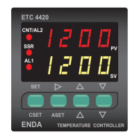
TEMPERATURE CONTROLLER
ENDA
PV
SV
CSET
ASET
SET
ETC 4420
CNT/AL2
AL1
AN/SSR
-
-
+
+
INDUSTRIAL ELECTRONICS
ETC4420-230VAC-RS
PID TEMPERATURE CONTROLLER
SN: XXXXXXXXX
6
3
2
1
7
4
8
5
CONT./AL2
AL1
AC 250V 2A
RESISTIVE LOAD
AC 250V 2A
RESISTIVE LOAD
230V AC +10% -20%
50/60Hz 5VA
TC
Pt 100
RS-485 COM.
14
15
9
10
11
12
13
RS- 485
SSR
OUT
A
B
+
-
ENDA
-
+
INDUSTRIAL ELECTRONICS
ETC4420-24VAC
PID TEMPERATURE CONTROLLER
SN: XXXXXXXXX
6
3
2
1
7
4
8
5
CONT./AL2
AL1
AC 250V 2A
RESISTIVE LOAD
AC 250V 2A
RESISTIVE LOAD
TC
Pt 100
14
15
9
10
11
12
13
+
-
ENDA
SSR
OUT
24V AC ±10%
50/60Hz 5VA
Order Code - : ETC4420-
1
1-
230VAC...230V AC
24VAC.....24V AC
Supply Voltage
2
2- Modbus Option
RS........RS-485 Modbus communication
None....Don’t support RS-485 Modbus communication
SM...........9-30V DC / 7-24V AC
SM...........9-30V DC / 7-24V AC
the panel:
- While pressing both side of
the device in direction 1, push it
in direction 2.
For removing the device from
1
2
1
87mm
Depth
Connection
cables
Enviroment temperature
measurement sensor
 Loading...