Do you have a question about the ENERGY KINETICS EK1 and is the answer not in the manual?
Instructions should be carefully read and kept for future reference to gain the best performance.
Inspect shipment for external damage. Store all parts safely and report any missing items.
Provide clearance to combustible surfaces and follow national codes for installation.
Connect Air Box to an outside air source for combustion air, recommended for tight construction.
Confined spaces need permanent openings for combustion air, ensuring adequate infiltration.
L-Vent chimney pipe is suitable for SYSTEM 2000 boilers due to lower flue gas temperatures.
Instructions for installing sidewall venting kits and ensuring proper air supply.
Lists approximate settings for oil burners based on testing, final settings require combustion test equipment.
Instructions for installing the oil burner, including the ceramic amulet and retort cement.
Follow base assembly instructions or mount on solid, level blocks. Boiler has a specific pitch for air removal.
Controls heating zones and domestic hot water using 24-volt zone valves for each zone.
Arrangement of the domestic hot water system. Insulation is recommended for fuel efficiency.
Fill system with water, keep vent cap open, and purge zones until a steady stream of water.
Covers boiler water treatment, anti-freeze, and winterizing procedures for system protection.
Connect 120V power from a dedicated circuit. Ensure proper grounding for all electrical accessories.
Digital Manager operates on 24-volt power. Thermostats require careful placement away from drafts.
Diagram illustrating low voltage wiring for the Digital Energy Manager and its components.
Instructions for mounting the Digital Manager to the junction box and connecting the quick connectors.
Details the function of each option switch on the Digital Manager for system customization.
Lists normal settings for the High Limit Aquastat and Hot Water Tank Thermostat.
Step-by-step guide for initial boiler start-up, including checks and adjustments.
Advises on setting Air-Fuel mixture conservatively based on installation conditions for efficient operation.
Instructions for checking draft, CO2/O2, stack temperature, and smoke test after 15 minutes of running.
Instructions for installing the expanded Digital Energy Manager with additional zone capabilities.
How to connect the Digital Energy Manager to a home security system for monitoring.
Guide to troubleshooting by observing Manager lights and temperature indicators for problem diagnosis.
Basic troubleshooting steps for common issues like the burner not running.
Test procedure for diagnosing intermittent zone heating issues.
Test procedure for addressing the 140F flashing light without a burner lockout.
How to test the digital temperature sensor, with warnings about applying voltage.
Explains the role of line voltage relays in controlling the burner, circulator, and inducer.
Details the surge suppression features on the system's relay board.
Explains what different flashing lights on the Manager indicate and potential causes.
How to place the Manager in "SERVICE BOARD MODE" for conventional boiler operation.
Explains Manager lights, their conditions, and corresponding diagnoses for troubleshooting.
Step-by-step instructions for cleaning the boiler's internal surfaces and flue passages.
Recommends replacing the ceramic sleeve "amulet" each time the air tube is removed for protection.
Provides instructions for replacing the combustion chamber if it becomes necessary.
Warranty covering defects in material and workmanship for three years from installation.
Covers Digital Energy Manager (5 years) and other supplied components per manufacturer.
Covers the pressure vessel for the lifetime of the original owner, with prorated charges after 10 years.
Instructions on how to obtain prompt warranty service and contact Energy Kinetics.
Form for the original owner to transfer the warranty to a new owner.
| Brand | ENERGY KINETICS |
|---|---|
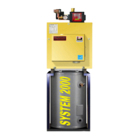
| Model | EK1 |
| Category | Boiler |
| Language | English |