1
2
INSTALLATION INSTRUCTIONS
DESCRIPTION
WIRING DIRECTIONS
3
SENSOR ADJUSTMENT
MPC-50H
High Bay 360° Passive Infrared Line Voltage
Occupancy Sensor
SPECIFICATIONS
Adjustable Light Level..................................................10FC—150FC
@ 120VAC, .............................................................0-800W ballast or tungsten
Voltage ...........................................................120/277VAC, 50/60Hz
Load Requirements:
@ 277VAC, ..............................................................................0-1200W ballast
@ 120VAC ...............................................................................................1/4 hp
Adjustable Sensitivity.................................50% or 100%(DIP switch)
Operating Temperature ................................32°to 131°F (0°to 55°C)
Relative Humidity .......................................20-90%, non-condensing
Material........................................................................................ABS
Coverage:
MPC-50H-L1: Mounting height: 50ft Field of view: 360° Coverage :2800 sq.ft
MPC-50H-L2: Mounting height: 8ft Field of view: 360° Coverage :1200 sq.ft
The MPC-50H 360 ° occupancy sensor uses advanced PIR technology to
turn on the lights when motion is detected and keep the lights on when
movement is present. The sensor will automatically turn off the lights if no
movement is detected within the amount of time selected in the time delay.
The MPC-50H is specially designed for use in areas with high ceilings such
as warehouses, distribution centers, and gymnasiums. Be sure to attach the
appropriate lens based on the ceiling height.
There are two lens choices available, lens 1 and lens 2. Lens 1 is an
extended range lens that provides up to 2800 sq. ft. of coverage at a
maximum installation height of 50 ft.
Lens 2 is a high density lens that provides up to 1200 sq. ft. of coverage at a
maximum installation height of 8 ft.
The sensor may be adjusted to operate at the desired level of light under normal
lighting conditions of the immediate area.
To do so, turn the dial to point the arrow toward
the “-”sign for sensor to detect motion and
operate during low light or no light.
Point the arrow toward the “+”sign for
sensor to operate when there’s more light in the
area or even during daylight.
NOTE: The light level is adjustable only when
the time delay is set at or above 30 seconds.
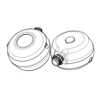
Lens choices:
The coverage area is determined by the type of lens attached to the
MPC-50H. (See Figure 1).
MPC-50H-L1
Extended Range (Lens 1)
MPC-50H-L2
High Density (Lens 2)
0.69"
0.65"
2.60"
0.70" 0.65"
2.61"
WARNING
Turn the POWER OFF at the circuit breaker before installing the
sensor
Read and understand these instructions before installing. This device
is intended for installation in accordance with the National Electric
Code and local regulations. It is recommended that a qualified
electrician performs
this installation. Make sure to turn off the circuit
breaker or fuse(s) and make sure power is off before wiring the
device. Use copper wire only, or equivalent
.
Refer to the wire diagram of the sensor (See Figure 2)
Neutral
Hot
Load
MPC-50H
Black
Red
White
Figure 2
1. Connect the hot wire to the black wire on the sensor
2. Connect the neutral wire to the white wire on the sensor
3. Connect the load wire to the red wire on the sensor
4. If using provided Housing, attach by aligning the arrow
on the MPC-50H with the Open arrow on the Housing,
then twist the device counterclockwise until the Close
arrows align.
5. Turn on Circuit Breaker
If the sensor detects occupancy during the warm-up, the time delay will
increase.
If no occupancy is detected during the warm-up,the light turns OFF after the
initial 60-second warm-up period.
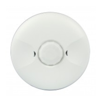
PIR Sensor
Surface
Mounting
Screw Hole
DIP Switches
Detection
Indicator LED
CDS
Light Level
Adjustment
Surface
Mounting
Screw Hole
Note: The LED indicator flashes during the 60-second
warm-up period when power is first applied
COVERAGE
LIGHT LEVEL ADJUSTMENT
Lens 1 at Max 50' high
Lens 2 at 8' high
22' Radius
30' Radius
Figure 1