8
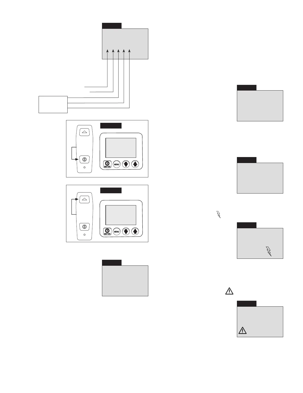
6.5 O “Diagnose” Menu
DIAGNOSE
00001
Pendant on/o button
Pendant advance button
(not used
on this pump
version)
Screen 15
PSI MPa
BAR Nm
Ft-lb
(See Screen 15) This screen allows
the operator to troubleshoot various
pendant problems. If the number “1”
does not appear when a pendant
button is pushed, problems with
the pendant button switches and/or
pendant cord may be present (See
Screens 16 and 17). Use Local mode
to operate pump until the problem can
be corrected. Refer to QRC step #11.
Press
Screen 16
DIAGNOSE
01001
PSI MPa
BAR Nm
Ft-lb
Diagnose screen
with pendant
on/o button
pushed.
Press
Screen 17
DIAGNOSE
10001
PSI MPa
BAR Nm
Ft-lb
Diagnose screen
with pendant
advance button
pushed
.
6.5 P “Calibration” Menu
0
SET
Screen 18
PSI
(See Screen 18) This screen allows
the operator to adjust the pressure
value shown on the LCD to match a
master gauge.
To access the Calibration menu, first
go to the Units menu.
Then, press and hold the shroud
Motor on/o button for 7 seconds. ENTRY CODE will appear
on the LCD.
Then, press and hold both the Down Arrow and Up Arrow
buttons for 7 seconds. CAL PT A will appear on the LCD.
See Table 2, “ZU4 Pressure Transducer Calibration”, located
near the end of this document. Follow the steps in the table to
perform calibration procedures.
6.6 LCD Fault Conditions
Any fault condition will shut down the pump and prevent it
from starting.
6.6 A Clearing a Fault Condition from the LCD
After the fault causing problem has been corrected, clear the
fault message from the LCD by disconnecting electrical power
from the pump. Wait until all characters clear the LCD (~ 20
seconds), then reconnect power.
6.6 B Power O Fault
Display: “POWER OFF”
OFF
Screen 19
See Screen 19) The Power O fault
occurs when the AC line power drops
to 65% or less of nominal voltage. The
pump will automatically shut-o the
valve solenoid and motor, and “Power
O” will be displayed on the LCD.
Note: The Power O message will also
appear for several seconds after the
pump has been disconnected from
electrical power.
6.6 C Button Fault
Display: “BUTTON FAULT”
FAULT
Screen 20
(See Screen 20) The Button fault
occurs when the microcontroller
detects that any button has been
pressed during the boot sequence
or if the shroud Motor on/o button
has been pressed for more than
3 seconds.
6.6 D Motor Overload Fault
Display: “MTR OVLD FAULT”
and “Motor Overload”
MTR OVLD
FAULT
Screen 21
MOTOR
OVERLOAD
(See Screen 21) The Motor Overload
fault occurs when the electrical current
draw exceeds the pre-set limit of
the pump’s internal circuit breaker.
The circuit breaker will automatically
reset in about 2 to 3 minutes after
the condition has been corrected.
However, before the pump can be
restarted, the operator must clear the fault by disconnecting
and reconnecting electrical power as described in Section 6.6 A.
6.7 LCD Low Voltage Warning
Display: “LOW VOLT” and “Low Voltage”
Screen 22
LOW
VOLTAGE
(See Screen 22) A “Low Voltage”
condition is defined as an operating
condition when the AC line power is
at or below 80% of nominal voltage.
While running the pump under this
condition, the “Low Voltage” signal will
flash on the LCD and the Low Voltage
hours will be counted and stored by
the microcontroller.