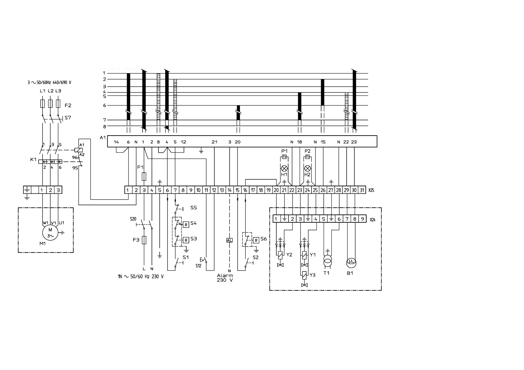
LIST OF COMPONENTS
A1 Oil burner control
B1 Photoresistor
F1 Operating fuse
F2 Fuse
F3 Fuse
H1 Lamp, low capacity
H2 Lamp, high capacity
K1 Thermal overload protection
M1 Burner motor
P1 Time meter, low capacity (optional)
P2 Time meter, high capacity (optional)
S1 Operating switch
S2 Operating switch, high/low capacity
S3 Control thermostat
S4 Temperature limiter
S5 Micro switch for hinged door
S6 Control thermostat, high/low capacity
S7 Main switch
S12 External reset button
S20 Main switch
T1 Ignition transformer
X24 Connection terminal board, burner
X25 Connection terminal board, switch box
Y1 Solenoid valve 1
Y2 Solenoid valve 2
Y3 Safety solenoid valve
Mains connection and fuse in accordance
with local regulations.
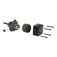
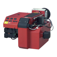
ELECTRIC EQUIPMENT
OIL BURNER CONTROL: LAL 3...
WIRING DIAGRAM
171 425 54 01-02