GENERAL INSTRUCTIONS
171 305 41 98-01
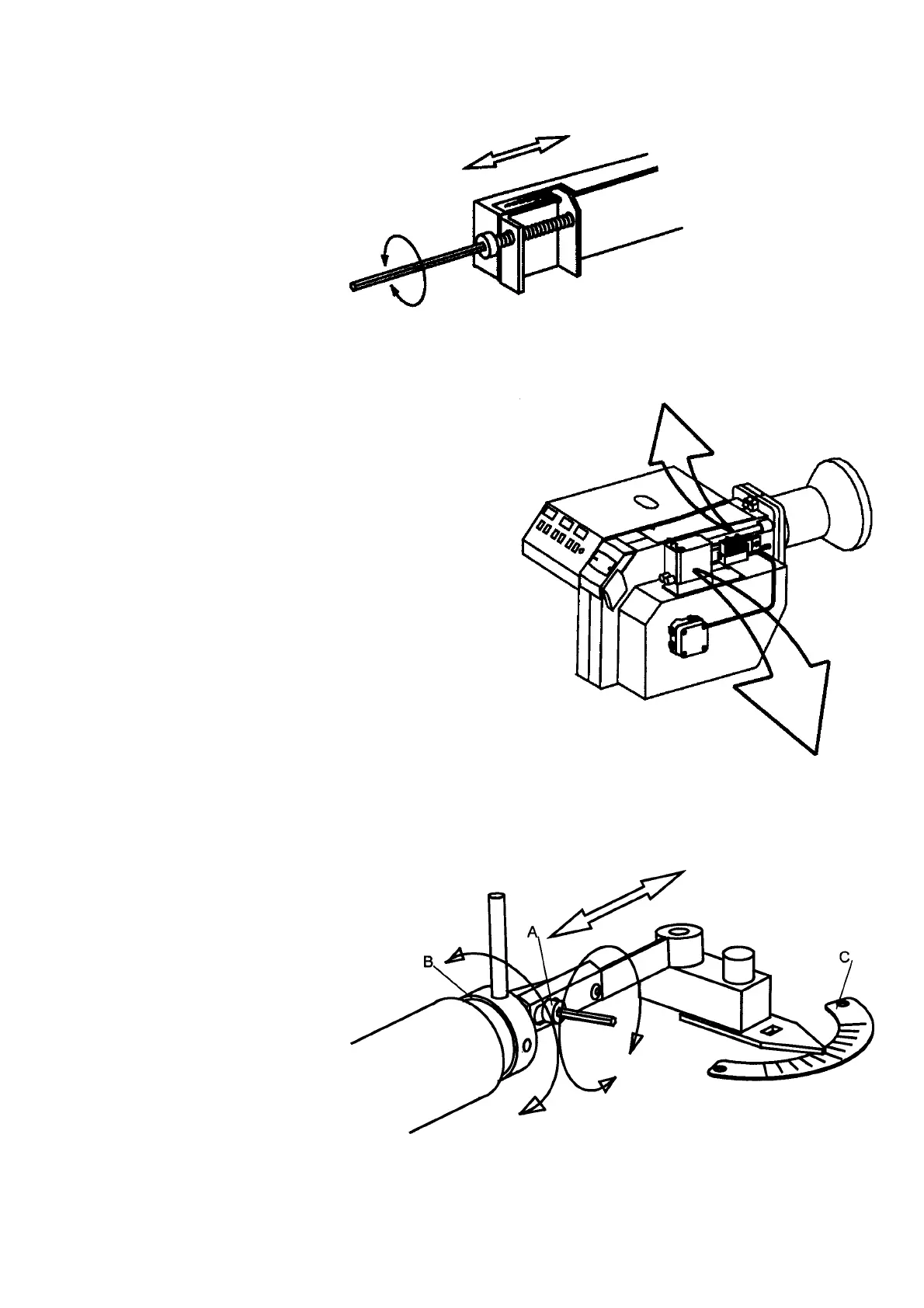
ADJUSTMENT OF NOZZLE
ASSEMBLY
Adjust the nozzle assembly with the
adjustment screw D to the desired
position.
AIR ADJUSTMENT
First stage:
Set the operating switch (S2) on low
capacity (I). Loosen the screw (A) and
turn the damper to the position wan-
ted. Tighten the screw (A) again.
Second stage:
Set the operating switch (S2) on high
capacity (II). Screw the knurled ring
(B) in (reduce) or out (increase). The
position of the damper can be read on
the damper scale (C).
Check the air adjustment by making a
flue gas analysis.