DJM2.4 MANUAL
15 Oct 00 R2
BMS signal at zero. The BMS signal should be calibrated as noted in section X. If the DJM2.4 is
being slaved to a C-TRAC, METASYS, or some other device, then there will not be a set point
connected to the DJM2.4. The setpoint is at the master control; therefore no discharge sensor
calibration is necessary.
TE6000 Sensor
If the system uses a TE 6000-960 sensor, it is wired with one side of the sensor to Terminal “B”
and the other side of the senor wired to both Terminals “D” and “SP”, then it is necessary to use
the set point on the DJM2.4. The set point is the small pot labelled “SP” (pot 5) and the setting is
as indicated on the label.
Using the Johnson TE 6000 series control, the DJM2.4 utilizes pot 1 (DCAL) as the "Discharge
Calibration" pot. Adjusting it CW = colder. With the burner-firing rate being stable (no hunting or
cycling) accurately measure the discharge temperature at the discharge temperature sensor.
Connect a DC meter to DJM2.4 terminals "OR" (positive) and "W". Set the discharge set point to
match the measured discharge temperature. Adjust pot 1 until the meter reading is 1.8 volts DC.
Note information below.
A second calibration method for the TE6000 without a meter is:
Ensure there is no signal (such as voltage on +/-) that would call for a higher discharge than the
temperature at the set point. Next, measure the temperature immediately next to the discharge
air sensor. Adjust the set-point dial (pot 5 labelled SP) to the same value as that measured at the
discharge sensor.
When this is complete adjust the DCAL (Pot1) until the heat light just goes off.
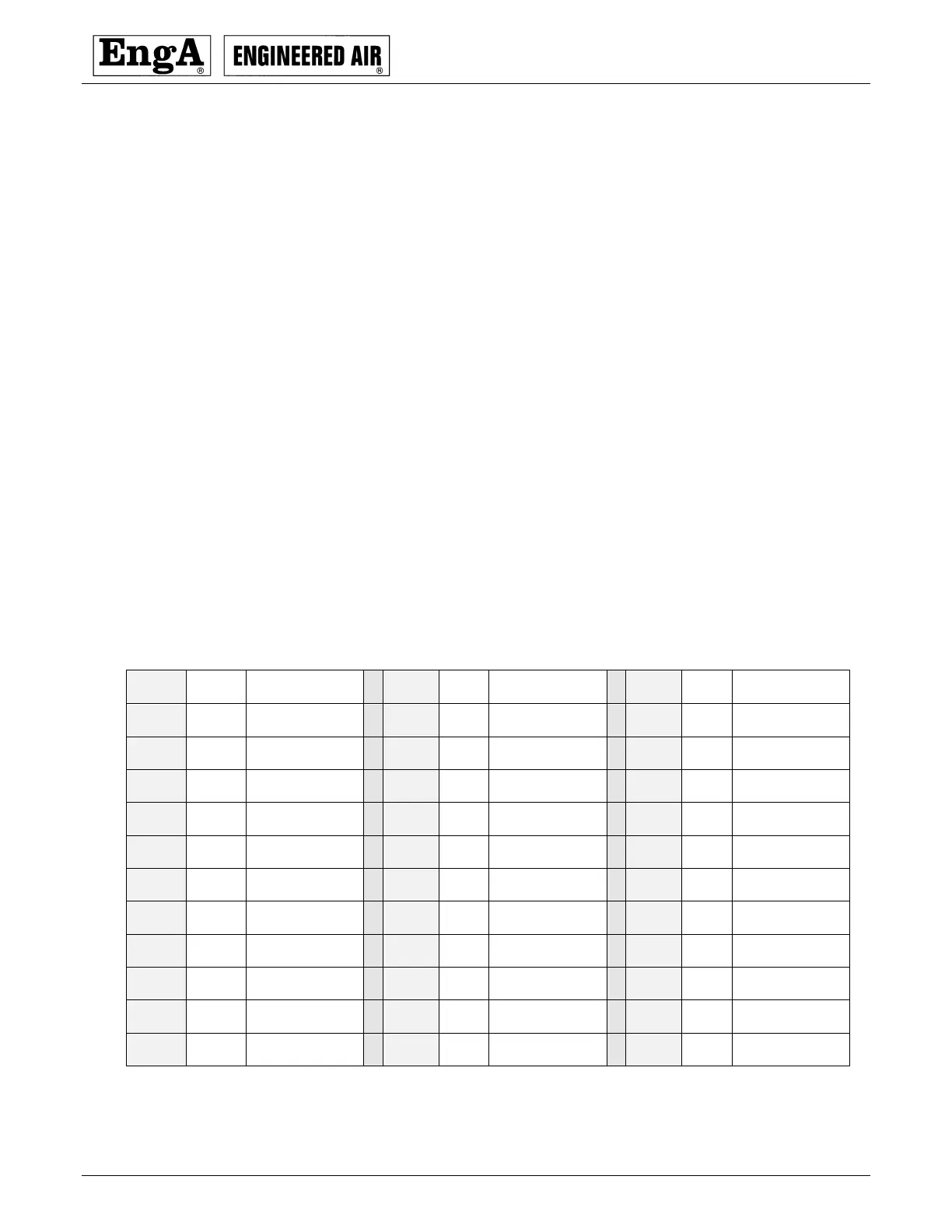
Sensor Resistance Chart for TE 6000-960
Reference resistance is 1035 ohms at 77°F. Resistance tolerances are ±0.05 to 0.15% at 77°F.
Temperature range +32 to +104°F.