A XES SC MANUAL
IOM-58 11 of 30 June 14 R5
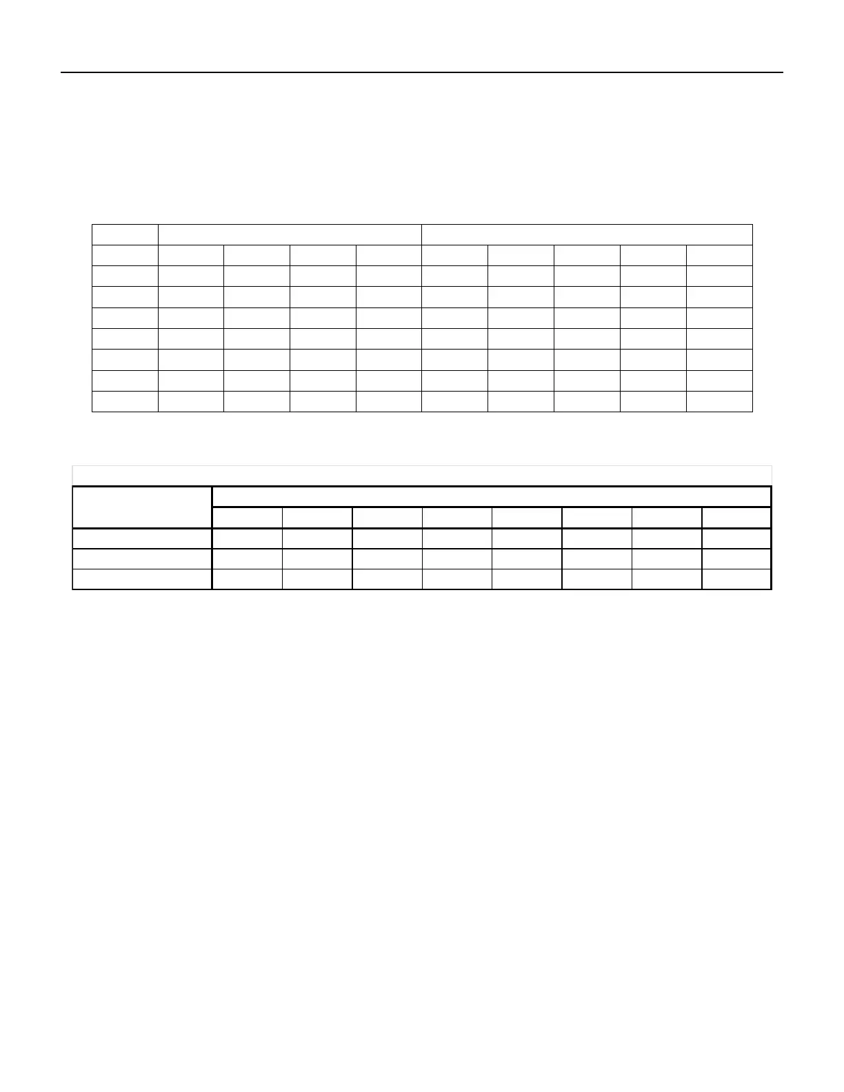
Table I indicates the maximum equivalent length of the various sizes of vent and combustion air for each
furnace model. Equivalent length equals the total length of straight pipe, plus the values for the fittings as
shown in the Table II below.
Table I
Combustion Air Diameter (inches)
Table II
Example: System Pipe Size = 5"
2 – 90° Elbows (5") = 2 x 9 = 18 ft.
5 - 4 ft. Lengths of 5" = 20 Ft.
Total Equivalent Feet = 18 ft. + 20 ft. = 38 ft.
This manual describes two options for separated combustion systems:
Side Wall Vent
o EngA Supplied
o By Others
Vertical Vent
COMBUSTION AIR DUCT
Each separated combustion XES heater shall be equipped with its own combustion air supply. It must not
connect to any other air intake systems.
Use single wall pipe constructed of minimum 24ga galvanized steel or a material or equal durability and
corrosion resistance. Single wall combustion air duct may be externally insulated, as required.
Each slip joint shall be secured with corrosion resistant screws or rivets, and sealed with an adhesive
silicon sealant and/or aluminum tape.
For horizontal combustion air systems longer than 5 ft (1.5m) the piping must be supported every 3 ft
(1m).
3 4 5 6 7 8 9 10
8 11 14 15 18 21 23 26
5 7 9 10 12 14 15 17
3 4 5 5 6 7 8 9
Equivalent length (feet) of vent or combustion air fittings
Vent or Combustion Air Diameter (inches)
 Loading...