EasyManua.ls Logo

ENGGA EVC600i - User Manual

ENGGA EVC600i
7 pages
Print Icon
To Next Page IconTo Next Page
Loading...
OPERATING MANUAL FOR AUTOMATIC VOLTAGE REGULATOR
MODEL NO : EVC600i
1. INTRODUCTION
2. ENVIRONMENTAL
3. TECHNICAL SPECIFICATION
The EVC600i Voltage Regulator is thyristor base to control the DC exciter field power of conventional
50 or 60 Hz brushless generators. The AVR circuitry includes under speed and over load protection
features. Excitation power is derived directly from the generator terminals.
-30 to 80°C (-22 to 176°F)
-40 to 80°C (-40 to 176°F)
Less than 2600 meter
<90%
2.1. Operating temperature:
2.2. Storage temperature:
2.3. ALTITUDE:
2.4. RELATIVE HUMIDITY:
Sensing Input
Power Input
Voltage Adjust Range
Field Resistance
Voltage Regulation
Output Voltage
Output Current
Terminal V -V for 220 Vac
Terminal V -V for 400 Vac
Voltage: 180 to 250 Vac
Frequency: 50 Hz or 60 Hz
180 - 300 Vac, 300 - 520 Vac
Recommend 9 - 24
< 1%
Maximum 90 Vdc @ 220 Vac
Maximum continuous: 8 A @ 220 Vac
10 second forcing: 10 A @ 220 Vac
0 220
0 380
Ω
±
Paralleling
Voltage Buildup
External Volts Adjustment
Thermal Drift
Analog Voltage Input
Current Compensation
Dimensions
Weight
Internal burden and adjustment for 0 to 10%
droop at 5 A, 0.8 PF, (from external CT)
4Vac, 30 Hz
At least 10% with 100k ohm 1 watt trimmer
0.05% per Degree C change in AVR ambient
In : 5A Input
At least 10 % @ P.F. = 0.8
175 mm L x 129 mm W x 37.5 mm H
530 10g
±
±5VDC, adjustable output voltage is no less than
2% for 1VDC (i.e. for ±5VDC it come out to be
±10%)
±
EVC600i
Generator Automatic Voltage Regulator
Operation Manual
Page 1 of 7
Updated 26Jan 2015
Question and Answer IconNeed help?

Do you have a question about the ENGGA EVC600i and is the answer not in the manual?

Overview

The ENGGA EVC600i is a thyristor-based Automatic Voltage Regulator (AVR) designed to control the DC exciter field power of conventional 50 or 60 Hz brushless generators. Its primary function is to regulate the generator's output voltage, ensuring stability and protection against various operational conditions. The AVR circuitry incorporates essential features such as under-speed protection and overload protection. Excitation power for the EVC600i is directly derived from the generator terminals, simplifying its integration into existing systems.

Important Technical Specifications:

The EVC600i is built to operate reliably across a wide range of environmental conditions. Its operating temperature spans from -30 to 80°C (-22 to 176°F), with an identical storage temperature range. It is suitable for altitudes less than 2600 meters and can withstand relative humidity levels below 90%.

Sensing Input:

The AVR offers flexible sensing input options:

  • Terminal Vo-V220 for 220 Vac systems.
  • Terminal Vo-V380 for 400 Vac systems.

Power Input:

  • Voltage: 180 to 250 Vac.
  • Frequency: 50 Hz or 60 Hz.

Output Specifications:

  • Output Voltage: Maximum 90 Vdc at 220 Vac.
  • Output Current: Maximum continuous 8 A at 220 Vac, with a 10-second forcing capability of 10 A at 220 Vac.

Voltage Regulation:

  • The EVC600i maintains voltage regulation to less than ±1%, ensuring stable power output.

Voltage Adjustment Range:

  • For 220 Vac systems: 180 - 300 Vac.
  • For 400 Vac systems: 300 - 520 Vac.

Field Resistance:

  • Recommended field resistance is between 9 and 24 Ω.

Paralleling Capability:

  • The AVR includes internal burden and adjustment for 0 to 10% droop at 5 A, 0.8 PF, with the signal derived from an external Current Transformer (CT).

Voltage Buildup:

  • Requires 4 Vac at 30 Hz for initial voltage buildup.

External Volts Adjustment:

  • Allows for an adjustment range of at least ±10% using a 100k ohm, 1-watt trimmer.

Thermal Drift:

  • Exhibits a low thermal drift of 0.05% per degree Celsius change in the AVR ambient temperature.

Analog Voltage Input:

  • Accepts ±5VDC, with an adjustable output voltage that is no less than 2% for 1VDC (meaning ±5VDC results in ±10% variation).

Current Compensation:

  • Designed for a 5A input.
  • Provides at least 10% compensation at a power factor of 0.8.

Physical Dimensions and Weight:

  • Dimensions: 175 mm (L) x 129 mm (W) x 37.5 mm (H).
  • Weight: 530 ± 10g.

Usage Features:

The EVC600i offers several features for flexible integration and precise control:

  • Mounting: The AVR can be mounted directly on the generator, switchgear, or control panel, provided it conforms to the specified mounting dimensions.
  • Sensing Input Voltage (Vo - V220 - V380): Supports both 220 Vac and 400 Vac generator outputs. For 220 Vac, sensing is between Vo and V220. For 400 Vac, sensing is between Vo and V380. The sensing connection should be "Line to Line" from the generator output.
  • Excitation Output (F+, F-): Connects to the brushless exciter field, with polarity needing to be observed.
  • Power Input (X1 & V0): For 400 Vac systems, X1 connects to the generator's Neutral and V0 to the V Phase. For 220 Vac systems, X1 connects to the U Phase and V0 to the V Phase.
  • Current Compensation Input (S1 - S2): Designed for a Current Transformer (CT) secondary current of 5A at 0.8 PF, enabling droop compensation for parallel operation.
  • External Voltage Adjustment (VR1 - VR2): An optional 100K / 1 watt potentiometer can be connected to these terminals for external voltage adjustment. If not used, these terminals should be left open.
  • Analog Voltage Input (A1 - A2): Allows for the injection of a fully isolated analog voltage (±5VDC max) from a PF controller or PLC, enabling up to 10% variation in terminal voltage.
  • DIP Switches (SW1, SW2):
    • SW1 (Response Time):
      • ON: Reduces AVR response time for 60Hz operation, adding fixed response time to the STAB POT setting to prevent over/under shoot during loading/unloading.
      • OFF: Standard response time for 50Hz operation, where STAB POT setting is optimal.
    • SW2 (UFRO Frequency):
      • ON: Configures Under Frequency Roll-Off (UFRO) for 60 Hz operation.
      • OFF: Configures UFRO for 50 Hz operation.

Maintenance Features:

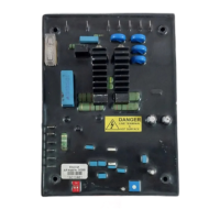
The EVC600i incorporates several adjustable trimmers for fine-tuning and protection, located on the back of the AVR board (except for the O/L Trimmer, which is referenced in Figure 1). These trimmers include DROOP, TRIM, UFRO, STAB, and VOLT.

  • VOLT (Voltage Adjustment):
    • Allows adjustment of the generator output voltage using the onboard trimmer or an external 100K ohm 1W trimmer.
    • Factory set for 400 Vac. If the setting is disturbed, a procedure is provided to reset it by turning the trimmer fully anti-clockwise, starting the generator, and slowly turning it clockwise until the desired voltage is reached.
  • STAB (Stability Adjustment):
    • Factory set for optimum performance. If adjustment is needed, rotate clockwise until voltage starts oscillating fast, then slowly counter-clockwise until stable.
  • UFRO (Frequency Roll-Off Adjustment):
    • Factory preset to cause voltage drop when frequency falls below 56.8-57.2 Hz (60 Hz) or 46.8-47.2 Hz (50 Hz).
    • A procedure is provided to reset the roll-off point by adjusting the prime mover RPM and then using the UFRO trimmer to turn the UFRO LED ON/OFF as required.
  • DROOP (Droop Adjustment):
    • For generators intended for parallel operation, a quadrature droop CT (connected to S1 and S2) provides a power factor dependent signal.
    • The DROOP POT allows adjustment of droop from 0% (fully anti-clockwise) to 10% (fully clockwise) at 0.8 PF, with a 5A CT secondary current. Factory set to 0% for solo operation.
  • TRIM (Analog Voltage Input Adjustment):
    • This pot decreases the effect of the analog input voltage (on A1-A2) on the generator output.
    • Fully anti-clockwise results in no variation, while fully clockwise provides maximum effect (0 to 10% variation at ±5VDC).
  • O/L (Overload Protection):
    • Protects the generator from overloading by monitoring field current.
    • If the field current exceeds a set value (adjustable via the O/L POT), an internal timer starts. If the overload persists for 20 seconds, the AVR cuts off field voltage, shutting down the generator. The O/L LED indicates an O/L Trip.
    • Adjustable from 0.1A to 8A DC. Factory set to 8 Amps DC.

Operational Test:

A simple operational test procedure is outlined to verify the basic functionality of the EVC600i, involving connecting the AVR to a 230 Vac 50 Hz supply and observing the behavior of a connected lamp while adjusting the VOLT trimmer. This test confirms the regulator's ability to control voltage, though full stability testing requires operation with a generator.

All voltage readings should be taken with an average-reading voltmeter. It is crucial not to use Meggers or high-potential test equipment with the AVR connected to the generator, as this could damage the AVR.

ENGGA EVC600i Specifications

General IconGeneral
BrandENGGA
ModelEVC600i
CategoryController
LanguageEnglish