A base
IOM67 6 February 2021 R0
Click OK to accept, and then open a web browser
and type in the following address to gain access to
the display interface:
192.168.0.10:8080/webvisu.htm
To simplify connections, make this a bookmark in
the web browser for future connections.
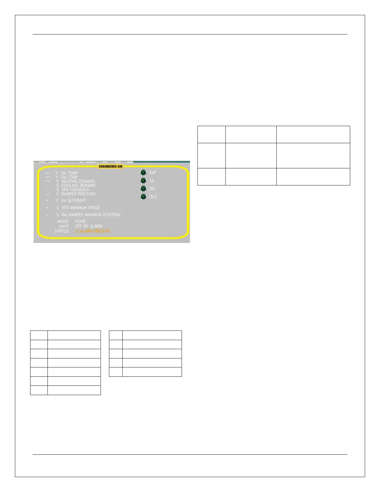
The display interface should appear, similar to the
following. Note the tabs along the top for access
to additional information screens.
Changes made to adjustable values are ‘live’.
Pressing ENTER or SAVE is not required.
Heating and Cooling Display Sequence Definitions
The display screens specific to gas fired heating
and mechanical cooling have a number sequence
included to describe the current operating mode.
ALARM RESET
Alarms may be reset either from the laptop
computer alarm screen or the red reset button near
the top left.
LED LIGHTS
ON=Powered
OFF=No Power to H&N
BLINK=Comm to CD-XM
ON=Internal Comm.
OFF=Failure
ON=Alarm Condition
OFF=No alarm present
SEVEN SEGMENT DISPLAY
Left is mode indication
4: Cooling
3: Heating
2: Economizer
1: Ventilation
Right 2 Displays: Alarm value
See ALARMS